Energy conservation and emission reduction method beneficial to carbon neutralization flue gas waste heat recovery and reheating technology

A technology for energy saving, emission reduction, and flue gas waste heat, which is applied in the field of flue gas treatment, and can solve problems such as heat waste, flue gas heat cannot be reused more effectively, and heat cannot be collected.

Inactive Publication Date: 2022-01-14
衡水市高新区博元新能源技术研发中心
View PDF1 Cites 0 Cited by
  • Summary
  • Abstract
  • Description
  • Claims
  • Application Information

AI Technical Summary

Problems solved by technology

[0004] In order to solve the above technical problems, the present invention provides an energy-saving and emission-reduction method that is beneficial to carbon-neutral flue gas waste heat recovery and reheating technology to solve the problem of flue gas treatment similar to the flue gas treatment method in the above patent. The heat in the flue gas cannot be collected during the gas cooling process, thus causing waste of heat, and the heat in the flue gas cannot be reused more effectively

Method used


Image

  • Energy conservation and emission reduction method beneficial to carbon neutralization flue gas waste heat recovery and reheating technology
  • Energy conservation and emission reduction method beneficial to carbon neutralization flue gas waste heat recovery and reheating technology
  • Energy conservation and emission reduction method beneficial to carbon neutralization flue gas waste heat recovery and reheating technology

Examples


Embodiment

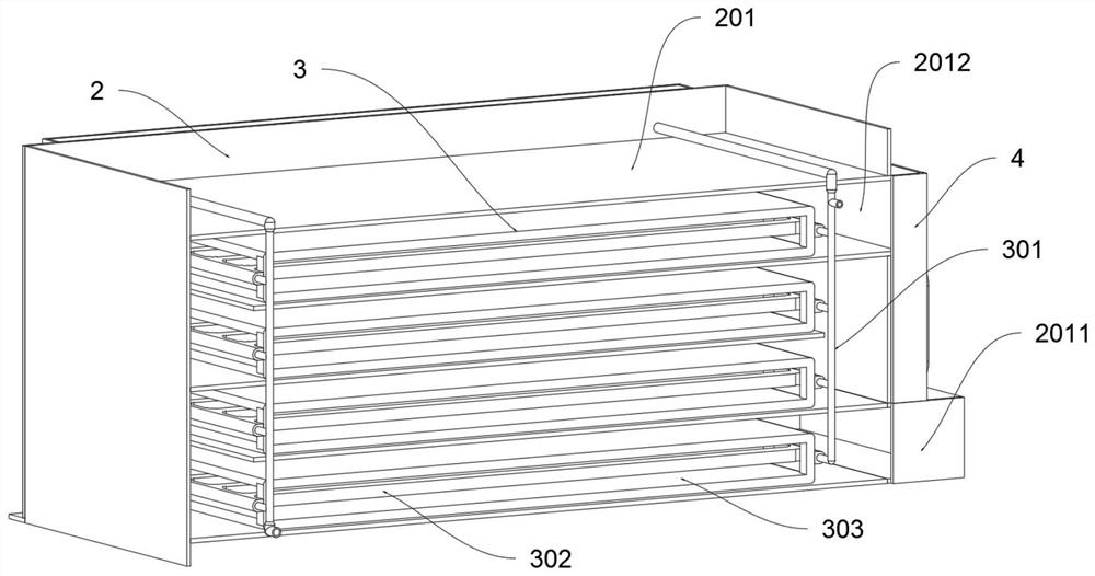
[0031] as attached figure 1 to attach Figure 7 Shown:

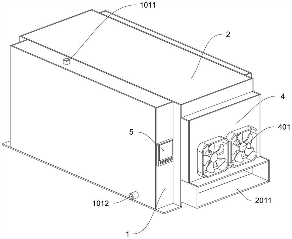
[0032] The present invention provides an energy-saving and emission-reduction method that is beneficial to carbon-neutral flue gas waste heat recovery and reheating technology. The energy-saving and emission-reduction method uses energy-saving and emission-reduction equipment to realize waste heat recovery and reheating of flue gas. Row equipment includes:

[0033] The waste heat exchange box 2; the waste gas discharge cover 4 is fixedly connected to the outside of the right side wall of the waste heat exchange box 2; the control instrument 5 is fixedly connected to the right outer wall of the circulation control box 1, and the control instrument 5 is electrically connected and controls the circulating water pump 102.

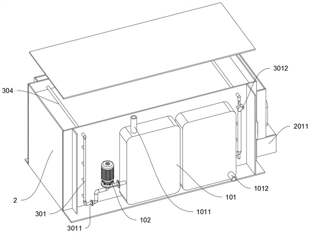
[0034] as attached figure 2 As shown, the circulation control box 1 is fixedly connected in front of the front wall of the waste heat exchange box 2; the circulation control box 1 includes a temperat...


PUM


Abstract

The invention provides an energy conservation and emission reduction method beneficial to a carbon neutralization flue gas waste heat recovery and reheating technology. According to the energy conservation and emission reduction method, waste heat recovery and reheating of flue gas are achieved through energy conservation and emission reduction equipment. The energy conservation and emission reduction equipment comprises a waste heat exchange box, wherein a circulating control box is fixedly connected to the front portion of the front wall of the waste heat exchange box and comprises a temperature storage water tank; the temperature storage water tank is fixedly connected to the interior of the circulating control box; the right side of the temperature storage water tank is connected with a low-temperature liquid inlet; the temperature storage water tank comprises a water tank circulating water inlet; the water tank circulating water inlet is formed above the left side of the temperature storage water tank; the water tank circulating water outlet is formed below the right side of the temperature storage water tank; a circulating water pump is arranged in the circulating control box, a water outlet of the circulating water pump is connected with the left side of the temperature storage water tank, and a water inlet of the circulating water pump is connected with a high-temperature liquid outlet; and four sets of inner exchangers are arranged in the waste heat exchange box, recycled heat can be used for preheating production materials, the effects of energy conservation and emission reduction are achieved, meanwhile, the temperature of flue gas is lowered, and pollution caused by the flue gas to the surrounding environment is reduced.

Description

technical field [0001] The invention belongs to the technical field of flue gas treatment, and more specifically relates to an energy-saving and emission-reducing method beneficial to carbon-neutral flue gas waste heat recovery and reheating technology. Background technique [0002] As a new form of environmental protection, carbon neutrality has been adopted by more and more large-scale events and conferences. Carbon neutrality can promote green life and production, and realize the green development of the whole society. In order to better achieve carbon neutrality, the flue gas treatment equipment can be used to treat the flue gas before it is discharged. Among them, there is a cooling method for the flue gas , flue gas filtration and other treatments can reduce the impact of flue gas on the surrounding environment. For example, application number: CN201710251493.X The present invention discloses a flue gas treatment device for chemical smelting equipment. [0003] Based...

Claims


Application Information

Patent Timeline
Patent Type & Authority Applications(China)
IPC IPC(8): F28D7/16F28F9/00F28F27/00
CPCF28D7/163F28F27/00F28F9/005
Inventor 李海青
Owner 衡水市高新区博元新能源技术研发中心
Why Eureka
Try Eureka