
Piezoelectric ultrasonic guided wave detection device and method

A piezoelectric ultrasonic and detection device technology, which is applied to the analysis of solids using sound waves/ultrasonic waves/infrasonic waves, the use of sound wave emission technology for material analysis, and instruments. , can not effectively reduce crosstalk and other problems, to achieve the effect of reducing reflection oscillation, high stability, reducing noise and harmonic components

Active Publication Date: 2022-01-14
SHANDONG UNIV
View PDF18 Cites 1 Cited by
  • Summary
  • Abstract
  • Description
  • Claims
  • Application Information

AI Technical Summary

Problems solved by technology

[0007] (1) The transmission waveform for driving the piezoelectric sensing element cannot be accurately controlled, the harmonic component of the waveform is relatively large, and the waveform is prone to resonance at high frequencies, resulting in relatively poor system stability;
[0008] (2) It is impossible to make timely protection against the short circuit of the piezoelectric sensing element;
[0009] (3) Cannot effectively reduce crosstalk between channels caused by waveform transmission
[0010] (4) Because different materials have different degrees of attenuation to ultrasonic waves, under the same transmitted signal, the received signal amplitude of different materials will be hundreds of times different, so a single device cannot simultaneously monitor aluminum alloys, composite materials, etc. many types of structures

Method used


Image

  • Piezoelectric ultrasonic guided wave detection device and method
  • Piezoelectric ultrasonic guided wave detection device and method
  • Piezoelectric ultrasonic guided wave detection device and method

Examples


Embodiment 1

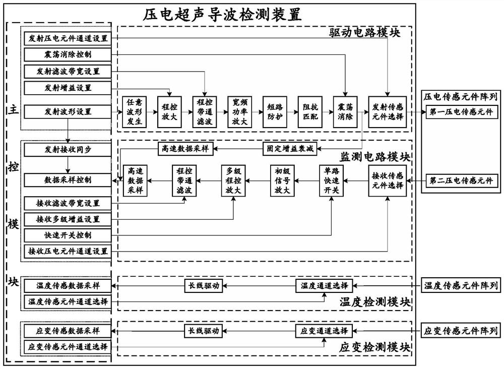
[0068] Such as figure 1 As shown, Embodiment 1 of the present invention provides a piezoelectric ultrasonic guided wave detection device, including: driving and monitoring of piezoelectric sensing elements, monitoring of temperature sensing elements and strain sensing elements.

[0069] When using piezoelectric sensing elements for structural damage monitoring, paste multiple piezoelectric sensing elements on the structure to be tested, use one piezoelectric sensing element to transmit a high-voltage driving signal, and use another piezoelectric sensing element to receive Response signal, if the structure is damaged, the response signal will carry damage information.

[0070] Therefore, the piezoelectric sensing element part mainly includes two parts: the driving circuit and the monitoring circuit, and the main control module performs overall coordinated control of all circuits of the entire instrument.

[0071] The driving part of the piezoelectric sensing element is compose...

Embodiment 2

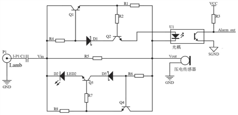
[0092] Embodiment 1 of the present invention provides a piezoelectric ultrasonic guided wave detection device, including each specific module in Embodiment 1, wherein a specific example of a short circuit protection module is given, as figure 2 shown, including:

[0093] The electrical signal input terminal Vin is connected to the signal output terminal V through the fifth resistor R5 OUT connection, signal output V OUT It is used to connect with the emitting piezoelectric sensing element, the signal input end is respectively connected with the first end of the fourth resistor R4 and the collector of the first triode Q1, and the emitter of the first triode Q1 is respectively connected with the first resistor The first end of R1 is connected to the first end of the second resistor R2, and the second end of the second resistor R2 is connected to the base of the second transistor Q2;

[0094] The second terminal of the fourth resistor R4 is respectively connected to the base o...

Embodiment 3

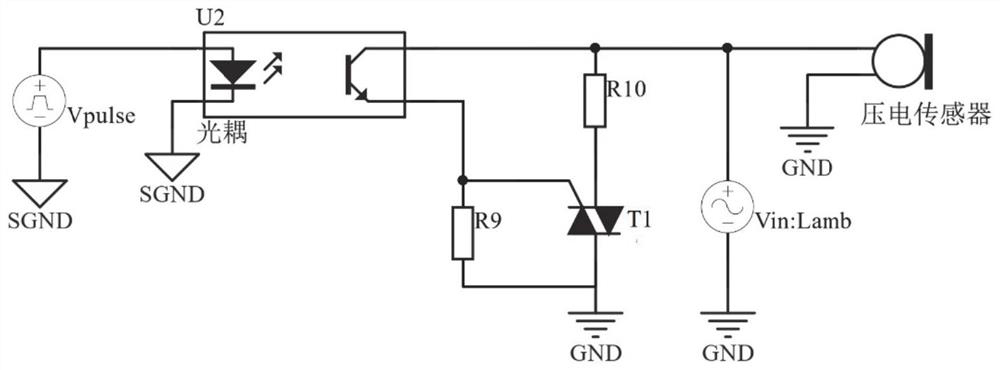
[0103] Embodiment 1 of the present invention provides a piezoelectric ultrasonic guided wave detection device, including each specific module in Embodiment 1, wherein a specific example of an oscillation elimination module is given, as image 3 shown, including:

[0104] The Lamb wave signal input terminal Vin is respectively connected to the transmitting piezoelectric sensing element, the third terminal of the second optocoupler U2, and the first terminal of the tenth resistor R10; the second terminal of the tenth resistor R10 is connected to the first terminal of the first bidirectional thyristor T1 The first end is connected, the gate of the first two-way thyristor T1 is connected to the fourth end of the second optocoupler U2, and the first end of the ninth resistor R9, the third pin of the first two-way thyristor T1 is connected to the first end of the ninth resistor R9 Both ends are grounded.

[0105] The first end of the second optocoupler is connected to the pulse inp...


PUM


Abstract

The invention provides a piezoelectric ultrasonic guided wave detection device and method. The piezoelectric ultrasonic guided wave detection device comprises a main control module, a driving circuit module, a monitoring circuit module, a temperature detection module, a strain detection module, at least two piezoelectric sensing elements, at least one temperature sensing element and at least one strain sensing element, wherein the main control module is connected with the at least one first piezoelectric sensing element through the driving circuit module, the at least one second piezoelectric sensing element is connected with the main control module through the monitoring circuit module, the main control module is connected with at least one temperature sensing element through the temperature monitoring module, and the main control module is connected with at least one strain sensing element through the strain monitoring module. According to the invention, the stable control of the transmitted signal is realized, the resonance of the transmitted signal is eliminated, and the noise of the transmitted signal is reduced; timely protection and alarm prompt for short circuit of the piezoelectric sensing element are realized; the crosstalk between the channels is eliminated; and the applicability of the instrument under different working conditions is improved.

Description

technical field [0001] The invention relates to the field of structural health monitoring, in particular to a detection device and a detection method based on piezoelectric ultrasonic guided waves. Background technique [0002] The statements in this section merely provide background art related to the present invention and do not necessarily constitute prior art. [0003] Structural health monitoring is a description of whether the working state of the structure is normal or not. Sensors are used to obtain structural operating parameters, and the characteristic information required for health status diagnosis is obtained through data processing. By fusing various characteristic information, the status monitoring, fault diagnosis, and prediction of the structure are realized, and health status information that can be used for maintenance and decision-making is generated. [0004] Piezoelectric sensing elements, also known as piezoelectric transducers, are devices that use t...

Claims


Application Information

Patent Timeline
Patent Type & Authority Applications(China)
IPC IPC(8): G01N29/04G01N29/14
CPCG01N29/04G01N29/14G01N2291/0289
Inventor 姜明顺魏钧涛张雷张法业隋青美贾磊
Owner SHANDONG UNIV
Learn More