Exhaust structure of control cabinet

A control cabinet and cabinet body technology, applied in the field of control cabinets, can solve the problems of corrosion and damage of the control cabinet, easy adhesion of moisture, moisture ingress, etc., and achieve the effect of good cooling effect.

Inactive Publication Date: 2022-01-14
上海嘉晨成套电气控制设备有限公司
View PDF0 Cites 0 Cited by
  • Summary
  • Abstract
  • Description
  • Claims
  • Application Information

AI Technical Summary

Problems solved by technology

[0003] When the control cabinet is in use, it needs to have a good heat dissipation structure. When ensuring heat dissipation, it needs to draw in external air to cool down, and then discharge the hot air through the exhaust structure. The ambient humidity around the control cabinet of the water pump station is generally relatively low. , in the process of drafting and exhausting, it is easy to cause moisture to enter the inside of the control cabinet, and the moisture is easy to coat the inside of the control cabinet and cannot be released, which will easily lead to corrosion and damage inside the control cabinet

Method used


Image

  • Exhaust structure of control cabinet
  • Exhaust structure of control cabinet
  • Exhaust structure of control cabinet

Examples


Embodiment Construction

[0028] In order to make the technical means, creative features, achievement goals and effects realized by the present invention easy to understand, the present invention will be further described below with reference to the specific embodiments.

[0029] In the description of the present invention, it should be understood that the terms "upper", "lower", "front", "rear", "left", "right", "top", "bottom", "inside", " The orientation or positional relationship indicated by "outside" is based on the orientation or positional relationship shown in the accompanying drawings, and is only for the convenience of describing the present invention and simplifying the description, rather than indicating or implying that the indicated device or element must have a specific orientation, so as to The specific orientation configuration and operation are therefore not to be construed as limitations of the present invention.

[0030] In the description of the present invention, it should be not...


PUM


Abstract

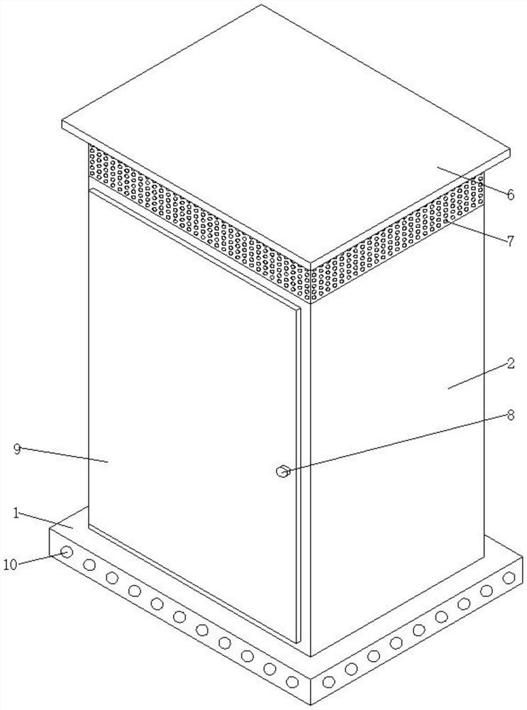
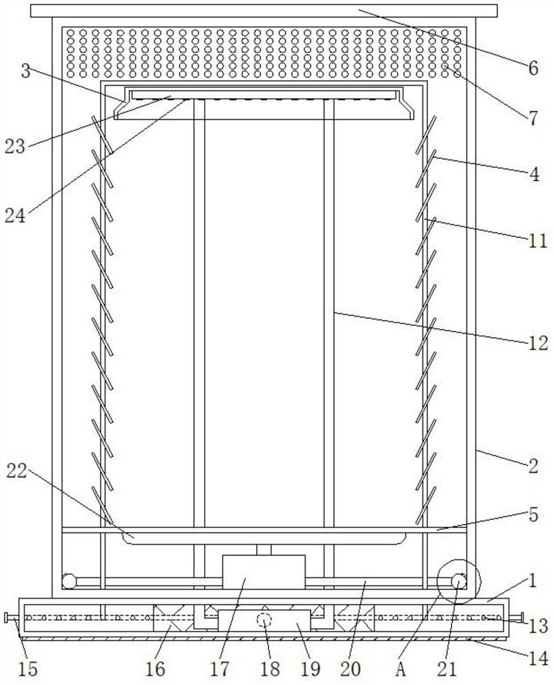
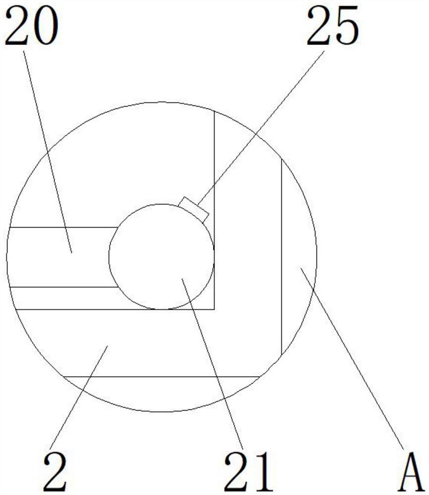
The invention relates to the technical field of control cabinets, and discloses a control cabinet exhaust structure which comprises a base, a cabinet body, an air outlet cover, an inclined plate and a supporting frame. The cabinet body is arranged on the upper surface of the base, the cabinet body is arranged in the middle of the surface of the base, a plurality of exhaust holes are formed in the outer ring surface of the upper portion of the cabinet body, the exhaust holes are evenly distributed in the upper surface of the cabinet body, a plurality of air inlet holes are formed in the outer ring surface of the base. And the plurality of air inlet holes are uniformly distributed on the surface of the base. A first air pump is arranged in the cabinet body, so that hot air in the cabinet body can be pumped into the cabinet body, then the hot air is discharged through an annular pipe and air blowing holes and is blown to the inner wall surface of the cabinet body, moisture entering the cabinet body is rapidly evaporated and discharged, and after external air enters the cabinet body through the interior of the base, the inner part of the cabinet body can be cooled by water in the inner annular copper pipe, and the inclined plate cooled by the upper copper pipe is matched, so that the inner part of the cabinet body can obtain a better cooling effect.

Description

technical field [0001] The invention relates to the technical field of control cabinets, in particular to a control cabinet exhaust structure. Background technique [0002] At present, the control cabinet is to assemble switchgear, measuring instruments, protective appliances and auxiliary equipment in a closed or semi-closed metal cabinet or on the screen according to the electrical wiring requirements. Endangers the safety of people and surrounding equipment. During normal operation, the circuit can be connected or disconnected with the help of manual or automatic switches, and the circuit can be cut off or alarmed with the help of protective electrical equipment in case of failure or abnormal operation. The measuring instrument can display various parameters in operation, and can also adjust some electrical parameters, prompt or send signals for deviation from the normal working state, and is often used in various power generation, distribution and substations. [0003] ...

Claims


Application Information

Patent Timeline
Patent Type & Authority Applications(China)
IPC IPC(8): H02B1/56H02B1/30H02B1/28H02B1/50H02B1/54
CPCH02B1/565H02B1/30H02B1/303H02B1/28H02B1/306H02B1/50H02B1/54
Inventor 石坚青
Owner 上海嘉晨成套电气控制设备有限公司
Why Eureka
Try Eureka