
Permanent magnet motor optimization design method considering operation condition

A permanent magnet motor, optimization design technology, applied in multi-objective optimization, design optimization/simulation, calculation, etc., can solve the problems of low optimization efficiency, many sampling points, and high design dimension, so as to improve optimization efficiency and improve algorithm search Performance and algorithm convergence, the effect of reducing computational cost

Pending Publication Date: 2022-01-18
JIANGSU UNIV
View PDF0 Cites 2 Cited by
  • Summary
  • Abstract
  • Description
  • Claims
  • Application Information

AI Technical Summary

Problems solved by technology

However, the direct combination of motor finite element analysis and algorithm requires motor finite element iterative operation of a large number of sample points, and the use of approximate models to replace the original motor model still has the problems of too many sampling points and low optimization efficiency due to high design dimensions

Method used


Image

  • Permanent magnet motor optimization design method considering operation condition
  • Permanent magnet motor optimization design method considering operation condition
  • Permanent magnet motor optimization design method considering operation condition

Examples


Embodiment Construction

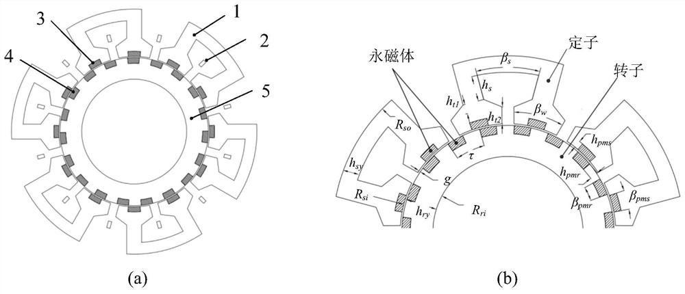
[0031] In order to illustrate the accuracy and advantages of the present invention more clearly, a detailed description will be given below in conjunction with a specific double permanent magnet motor.

[0032] figure 1 (a) is the topological structure of the motor. Part 1 in the figure is the stator core, part 2 is the stator winding, part 3 is the stator permanent magnet, part 4 is the rotor permanent magnet, and part 5 is the rotor core. The embodiment of the present invention is a three-phase motor with 12 slots / 12 pairs of poles stator permanent magnets / 19 pairs of poles rotor permanent magnets, the material of the stator and rotor core is DW540-50, and the material of the stator and rotor permanent magnets is NdFe35. The armature winding adopts a single-layer concentrated winding method. The magnetization methods of the stator and rotor permanent magnets are radial magnetization away from the center of the circle.

[0033] A kind of permanent magnet motor optimal desig...


PUM


Abstract

The invention discloses a permanent magnet motor optimization design method considering operation conditions. According to the method, operation condition analysis and multi-objective optimization are combined to carry out motor optimization design. The method comprises the following steps: firstly, determining representative working points and proportions thereof by adopting a K clustering method according to selected operation conditions; secondly, constructing a motor parameterized model, fitting a flux linkage model by adopting a response surface method, determining armature currents under maximum torque current ratio control or weak magnetic control of different representative points through a formula method, and effectively evaluating the electromagnetic performance of each representative working point; and finally, performing motor multi-objective optimization by taking the effective material cost and the working condition loss as optimization objectives. In the multi-objective optimization process, design variables are subjected to hierarchical optimization by adopting sensitivity analysis, single-parameter optimization is carried out on low-sensitivity variables, a response surface model is established for high-sensitivity variables, a Pareto solution set is generated by virtue of a multi-objective algorithm, and an optimal parameter combination of the motor is efficiently and accurately determined, so that the manufacturing cost of the motor is reduced, and the performance of the motor is improved.

Description

technical field [0001] The invention relates to an optimal design method of a permanent magnet motor considering operating conditions, and belongs to the field of optimal design of motors. Background technique [0002] With the depletion of petroleum resources and the enhancement of environmental awareness, the electrification process of the automobile industry has been continuously accelerated and deepened, which has become a globally recognized development direction. The advantages of electric vehicles, such as no pollution, low noise, and high energy efficiency, are expected to solve the three major problems of greenhouse gas emissions, energy consumption, and exhaust pollution in the transportation sector. As the most important part of the electric vehicle drive system, the motor should have a high torque density to ensure the acceleration capability required in the low-speed constant torque region and the magnetic field weakening capability required for speed expansion ...

Claims


Application Information

Patent Timeline
Patent Type & Authority Applications(China)
IPC IPC(8): G06F30/17G06F30/27G06K9/62G06F111/04G06F111/06
CPCG06F30/17G06F30/27G06F2111/06G06F2111/04G06F18/23213
Inventor 吉敬华沈人洁赵文祥徐亮凌志健
Owner JIANGSU UNIV
Learn More