
Quench protection circuit and electromagnetic ejection superconducting magnet

A technology of quench protection and superconducting magnets, which is applied in the fields of superconducting technology and electrical engineering, can solve problems such as large conduction voltage, increased heat leakage of the magnet system, and burnout of constant current switches, so as to achieve small system heat leakage and reliable The effect of strong operability and simple principle

Pending Publication Date: 2022-01-18
HIWING TECH ACAD OF CASIC
View PDF4 Cites 1 Cited by
  • Summary
  • Abstract
  • Description
  • Claims
  • Application Information

AI Technical Summary

Problems solved by technology

[0006] However, the existing quench protection circuit is mainly aimed at the quenching of static superconducting magnets, and the quench protection circuit has the following problems: (1) The protection diode is connected in series with the energy release resistor, resulting in a large conduction voltage of the branch , so the superconducting coil must first bear a large terminal voltage after quenching. If the energy release resistance is designed to be large, the insulation of the superconducting coil may have a breakdown risk; (2) the protective diode and the energy release resistor branch are at room temperature In the environment, the lead wire between it and the superconducting coil is the heat leakage source of the magnet system, which increases the heat leakage of the magnet system; (3) there are only one-way diodes. If the magnetization direction of the superconducting coil is opposite, the protection diode cannot play a role. Protection function; (4) When the superconducting magnet is in closed-loop operation, once the constant current switch is quenched, the two ends of the constant current switch will bear a large voltage and flow a large current, and the constant current switch may burn out; (5) The protection diode is connected in series with the energy release resistor. When the superconducting coil is quenched and the diode branch is turned on, due to the energy release resistor, the current of the superconducting coil decays quickly, which is beneficial to superconducting magnets in conventional applications. Yes, but it is unfavorable for short-term electromagnetic ejection superconducting magnets. The basic requirement of the quench protection circuit for electromagnetic ejection superconducting magnets is that when the superconducting coil is quenched, the magnetic field attenuates faster without damaging the superconducting coil. As slow as possible, make sure the residual magnetic field of the superconducting coil provides the braking force and prevents the superconducting magnet from colliding
Not suitable for dynamic superconducting magnets, especially in the field of ultra-high-speed short-duration electromagnetic ejection

Method used


Image

  • Quench protection circuit and electromagnetic ejection superconducting magnet
  • Quench protection circuit and electromagnetic ejection superconducting magnet
  • Quench protection circuit and electromagnetic ejection superconducting magnet

Examples


Embodiment Construction

[0019] It should be noted that, in the case of no conflict, the embodiments in the present application and the features in the embodiments can be combined with each other. The following will clearly and completely describe the technical solutions in the embodiments of the present invention with reference to the accompanying drawings in the embodiments of the present invention. Obviously, the described embodiments are only some, not all, embodiments of the present invention. The following description of at least one exemplary embodiment is merely illustrative in nature and in no way taken as limiting the invention, its application or uses. Based on the embodiments of the present invention, all other embodiments obtained by persons of ordinary skill in the art without creative efforts fall within the protection scope of the present invention.

[0020] It should be noted that the terminology used here is only for describing specific implementations, and is not intended to limit t...


PUM


Abstract

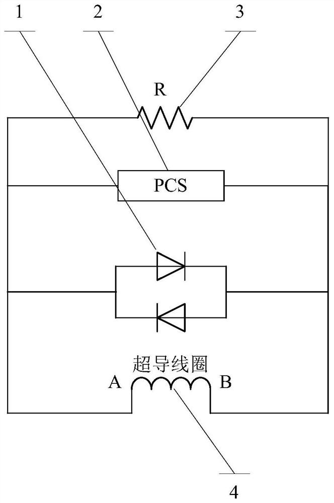
The invention relates to the technical field of superconducting technology and electrotechnics, and discloses a quench protection circuit and an electromagnetic ejection superconducting magnet. The circuit comprises two diodes, a constant-current switch and a protective resistor; the two diodes are connected in parallel reversely, the two diodes, the constant-current switch and the protective resistor which are connected in parallel reversely are all connected with the two ends of a superconducting coil in the superconducting magnet in parallel, and the protective resistor is used for protecting the constant-current switch. The quench circuit can protect the coil in different magnetizing directions, and no energy release resistor is arranged in the diode branch, so that the voltage at the two ends of the superconducting coil after quench is small, and the superconducting coil cannot be damaged. In addition, the two ends of the constant-current switch are connected in parallel with the protection resistor, so the irreversible damage of the constant-current switch due to large current and voltage after the constant-current switch is quenched can be prevented. The diode branch is not provided with an energy release resistor, and a protection resistor for protecting the constant current switch is small, so that the current attenuation is slow after the superconducting coil is quenched, and the residual magnetic field of the superconducting magnet can be utilized to generate the braking force.

Description

technical field [0001] The invention relates to the fields of superconducting technology and electrical engineering technology, in particular to a quench protection circuit and an electromagnetic ejection superconducting magnet. Background technique [0002] Electromagnetic catapult technology is an emerging linear propulsion technology, which is suitable for launching large loads in short strokes, and has broad application prospects in military, aerospace, civil and industrial fields. Electromagnetic ejection uses electromagnetic energy to push the ejected object outward, which is actually a form of electromagnetic gun. The core technology of electromagnetic ejection is driven by a linear motor, which generally has two structures: a long primary linear synchronous motor and a long secondary linear synchronous motor. For the ejection of large-load objects in a short stroke and reaching the ultra-high-speed level, it is generally required that the linear synchronous motor ca...

Claims


Application Information

Patent Timeline
IPC IPC(8): H02H7/00H01F6/00
CPCH02H7/001H01F6/00Y02E40/60
Inventor 张艳清陈慧星周伟毛凯韩树春张志华王新文刘坤王岩陈松
Owner HIWING TECH ACAD OF CASIC
Learn More