
Control method of direct current micro-grid system based on digital energy storage

A technology of DC microgrid and energy storage system, applied in the direction of load balancing, AC network load balancing, energy reserve, etc. in the DC network, it can solve the problem of reduced control effect and stability, great influence of power supply at the load end, and influence on the power supply of the system. Quality and other issues, to achieve the effect of unmanned management, suppression of bus voltage fluctuations, and bus voltage stability

Pending Publication Date: 2022-01-18
烟台东方能源科技有限公司
View PDF0 Cites 2 Cited by
  • Summary
  • Abstract
  • Description
  • Claims
  • Application Information

AI Technical Summary

Problems solved by technology

[0003] When the DC microgrid is operating in an isolated island, the power balance in the grid will seriously affect the power supply quality of the system, and even lead to system instability
If the voltage fluctuates greatly, the control effect and stability of each system in the grid will be reduced, and at the same time, it will have a great impact on the power supply at the load end. How to coordinate and control the power and voltage stability of the DC microgrid system has become a top priority.

Method used


Image

  • Control method of direct current micro-grid system based on digital energy storage
  • Control method of direct current micro-grid system based on digital energy storage
  • Control method of direct current micro-grid system based on digital energy storage

Examples


Embodiment Construction

[0049] The technical scheme of the present invention is described in detail below in conjunction with accompanying drawing:

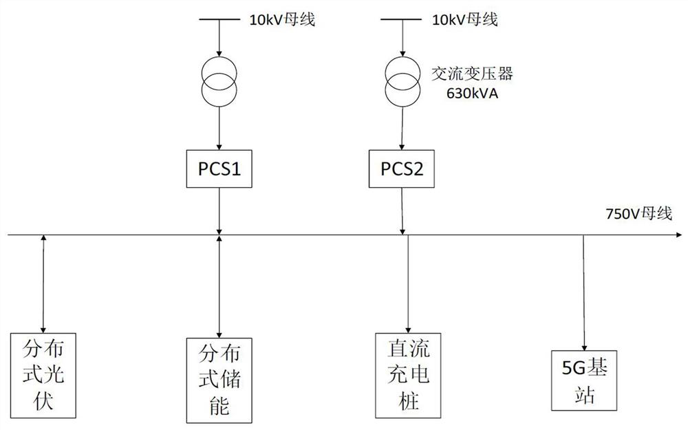
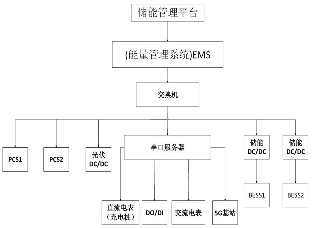
[0050] like figure 1 and figure 2 As shown, the DC microgrid system includes an energy storage management platform, EMS, PCS, energy storage system, photovoltaic system and DC load, the PCS is connected between the AC transformer and the DC bus, and the energy storage system, photovoltaic system and DC The loads are respectively connected to the DC bus, and the PCS, energy storage system, photovoltaic system and DC loads all exchange data with the energy management system EMS through the serial port server and the switchboard, and the energy storage management platform collects data through the EMS. PCS, energy storage system, photovoltaic system and DC load signals and issue control commands. The PCS includes parallel PCS1 and PCS2. In this embodiment, the DC load includes three 60kW DC charging piles and a 5G base station system. The energy storage ...


PUM


Abstract

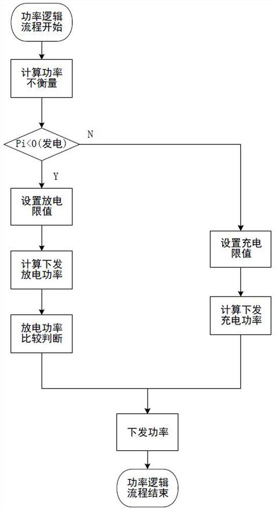
The invention discloses a control method of a direct current micro-grid system based on digital energy storage, which comprises the following steps that: when a system is in normal operation, the output power of a PCS1 is a power set value, and the output power of a PCS2 is a difference value between a system power unbalance amount and the power set value; when the direct current load suddenly changes, the output power of the PCS1 is automatically adjusted, and the instant output response power is used for supplying power imbalance caused by the sudden change of the direct current load, so that instant system power balance is realized; an EMS issues a control command to adjust the output power of the PCS2, the output power of the PCS1 automatically recovers to a power set value, and steady-state system power balance is achieved; and the control method also comprises the step that a charging and discharging process of the energy storage system is dynamically controlled according to relevant parameters such as the battery SOC, and bus voltage fluctuation is effectively restrained. By setting a reasonable power response mechanism and a charging and discharging control strategy, power stability and voltage stability of the micro-grid system are realized, and stable operation of the micro-grid is ensured.

Description

technical field [0001] The invention relates to the technical field of micro-grid intelligent control, in particular to a control method for a DC micro-grid system based on digital energy storage. Background technique [0002] A microgrid is a system unit composed of micropower sources, loads, energy storage systems, and control devices. Traditional microgrids usually include AC microgrids and DC microgrid systems. Compared with AC microgrids, DC microgrids are unique, diverse, controllable, and interactive, and have relative advantages in terms of simple connection, no need to consider voltage frequency phase, low cost and loss, etc. However, DC microgrids Involving energy storage, power generation and other DC load systems, the intelligent control and stable operation of the system is a very serious issue. [0003] When the DC microgrid operates in an isolated island, whether the power balance in the grid seriously affects the power supply quality of the system, and even ...

Claims


Application Information

Patent Timeline
Patent Type & Authority Applications(China)
IPC IPC(8): H02J1/14H02J3/32
CPCH02J1/14H02J3/32Y02E70/30
Inventor 张鑫李艳萍孙江涛彭晓宇李超
Owner 烟台东方能源科技有限公司
Learn More