Part welding and clamping device for high-end equipment manufacturing
A part welding and clamping device technology, which is applied in auxiliary devices, manufacturing tools, welding equipment, etc., can solve the problems of cumbersome operation process, low work efficiency, manpower consumption, etc., and achieve simple operation, improve work efficiency and ensure safety Effect
- Summary
- Abstract
- Description
- Claims
- Application Information
AI Technical Summary
Problems solved by technology
Method used
Image

Examples
Embodiment 1
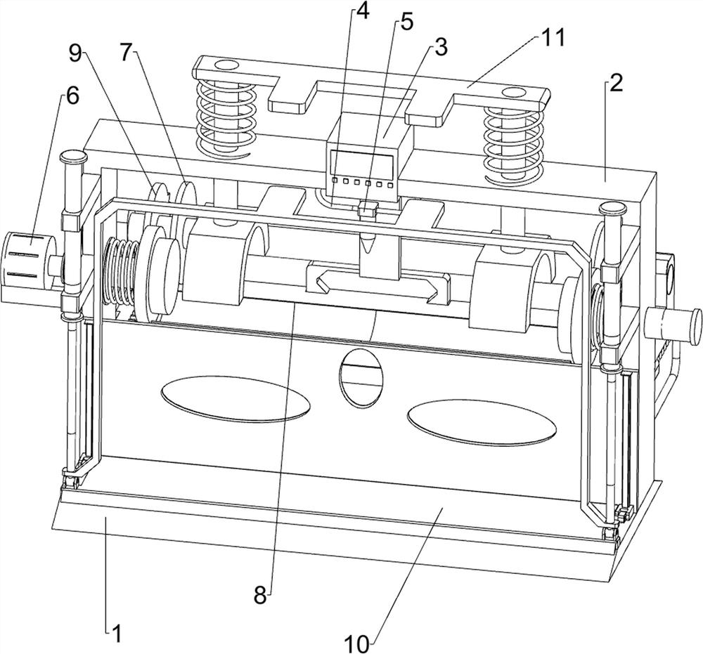
[0027] A part welding clamping device for high-end equipment manufacturing, such as Figure 1-2 As shown, it includes a base plate 1, a bracket 2, a central control panel 3, a first guide rod 4, a welding torch 5 and a driving mechanism 6, the top of the base plate 1 is connected with a bracket 2, the middle part of the bracket 2 is installed with a central control panel 3, and the inside of the bracket 2 A first guide rod 4 is connected to the top, and a welding torch 5 is slidably connected to the first guide rod 4 . The welding torch 5 cooperates with the central control panel 3 , and the bracket 2 is provided with a driving mechanism 6 .
[0028] Drive mechanism 6 includes servomotor 61, rhombus rod 62, rhombus sleeve 63, first clamping plate 64, first back-moving spring 65 and second clamping plate 66, and servomotor 61 is installed on the left side of support 2, on the output shaft of servomotor 61 A rhombus rod 62 is connected, and a rhombus sleeve 63 is slidably connec...
Embodiment 2
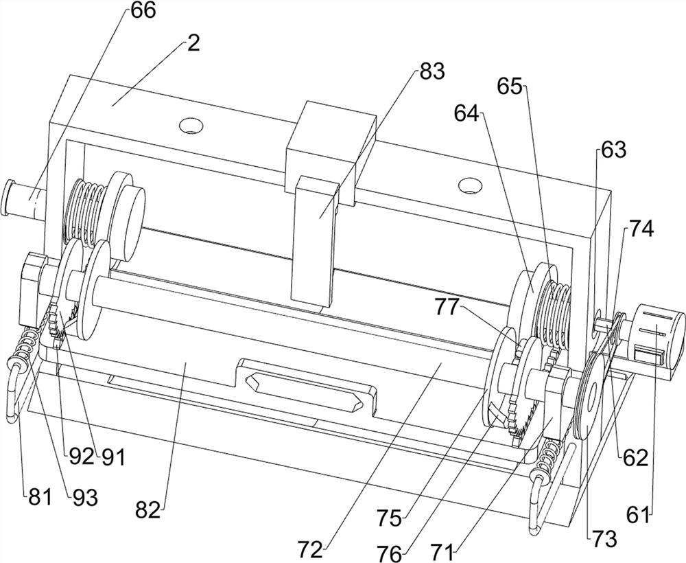
[0031] On the basis of Example 1, such as figure 2 As shown, transmission mechanism 7 is also included, and transmission mechanism 7 includes fixed block 71, rotating rod 72, belt pulley 73, flat belt 74, disc 75, extruding block 76 and contact rod 77, and the connection of support 2 rear side has Two fixed blocks 71, between two fixed blocks 71, rotating type is connected with rotating bar 72, is all connected with belt pulley 73 on the left side of rotating bar 72 and rhombus bar 62, is wound with flat belt 74 between two belt pulleys 73, rotates Both left and right sides of the bar 72 are connected with a disc 75, the disc 75 is connected with an extruding block 76, the first splint 64 and the second splint 66 are connected with a contact rod 77, and the contact rod 77 cooperates with the extruding block 76.
[0032] Rhombus rod 62 drives rotating rod 72 to rotate by belt pulley 73 and flat belt 74 when rotating, and rotating rod 72 rotates and drives disc 75 to rotate, an...
Embodiment 3
[0037] On the basis of Example 2, such as figure 2As shown, it also includes a rotary mechanism 9, the rotary mechanism 9 includes a sector gear 91, a rack 92 and a second return spring 93, the left and right sides of the rotating rod 72 are connected with sector gears 91, and the left and right sides of the top of the slide plate 82 are connected. There is a rack 92 , the sector gear 91 meshes with the rack 92 , and a second return spring 93 is connected between the slide plate 82 and the second guide rod 81 .
[0038] When the rotary rod 72 rotates, it drives the sector gear 91 to rotate. When the sector gear 91 rotates to mesh with the rack 92, the sector gear 91 continues to rotate and pokes the rack 92 to move backward, and the rack 92 moves backward to drive the slide plate 82 backward. Move, the second return spring 93 is compressed, and the slide plate 82 drives all the devices on it to move backward together when moving backwards. When the slide plate 82 moved backwa...
PUM
 Abstract
Description
Claims
Application Information
 - R&D
- Intellectual Property
- Life Sciences
- Materials
- Tech Scout
- Unparalleled Data Quality
- Higher Quality Content
- 60% Fewer Hallucinations
Browse by: Latest US Patents, China's latest patents, Technical Efficacy Thesaurus, Application Domain, Technology Topic, Popular Technical Reports.
© 2025 PatSnap. All rights reserved.Legal|Privacy policy|Modern Slavery Act Transparency Statement|Sitemap|About US| Contact US: help@patsnap.com