Optical element grinding and polishing device and machining method

A technology of optical components and polishing devices, which is applied in the direction of grinding devices, optical surface grinders, grinding/polishing equipment, etc., can solve the problems of small tool removal function changes, material removal instability, large and medium frequency ripple errors, etc., to achieve suppression Eliminate function instability and intermediate frequency ripple errors, improve component processing efficiency, and facilitate operation

Pending Publication Date: 2022-01-21
恒迈光学精密机械(杭州)有限公司
View PDF11 Cites 2 Cited by
  • Summary
  • Abstract
  • Description
  • Claims
  • Application Information

AI Technical Summary

Problems solved by technology

During the grinding and polishing of optical components, the small tool is pressed down (that is, the amount of pressure is increased), the movement axis is connected to the small tool ball head, so that the small tool always touches the surface of the optical component and the axis of the small tool is always perpendicular to the surface of the optical component; small During the tool lifting process (i.e., reducing the amount of pressing), the movement axis is separated from the small tool, and the effective load transfer is lacking, resulting in a change in the removal function of the small tool, resulting in an unstable amount of material removal; at the same time, the small tool axis and the surface of the optical element are no longer Vertical, prone to large IF ripple errors

Method used


Image

  • Optical element grinding and polishing device and machining method
  • Optical element grinding and polishing device and machining method
  • Optical element grinding and polishing device and machining method

Examples


Embodiment

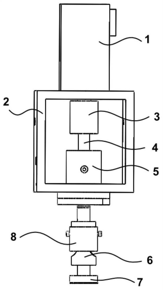
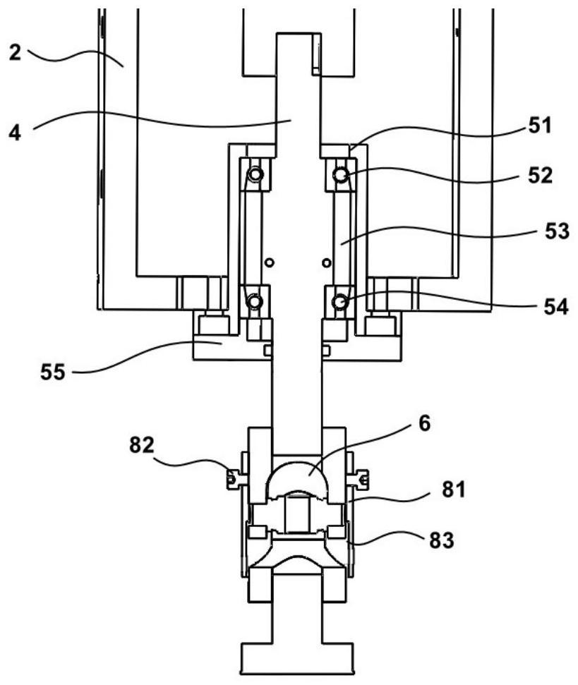
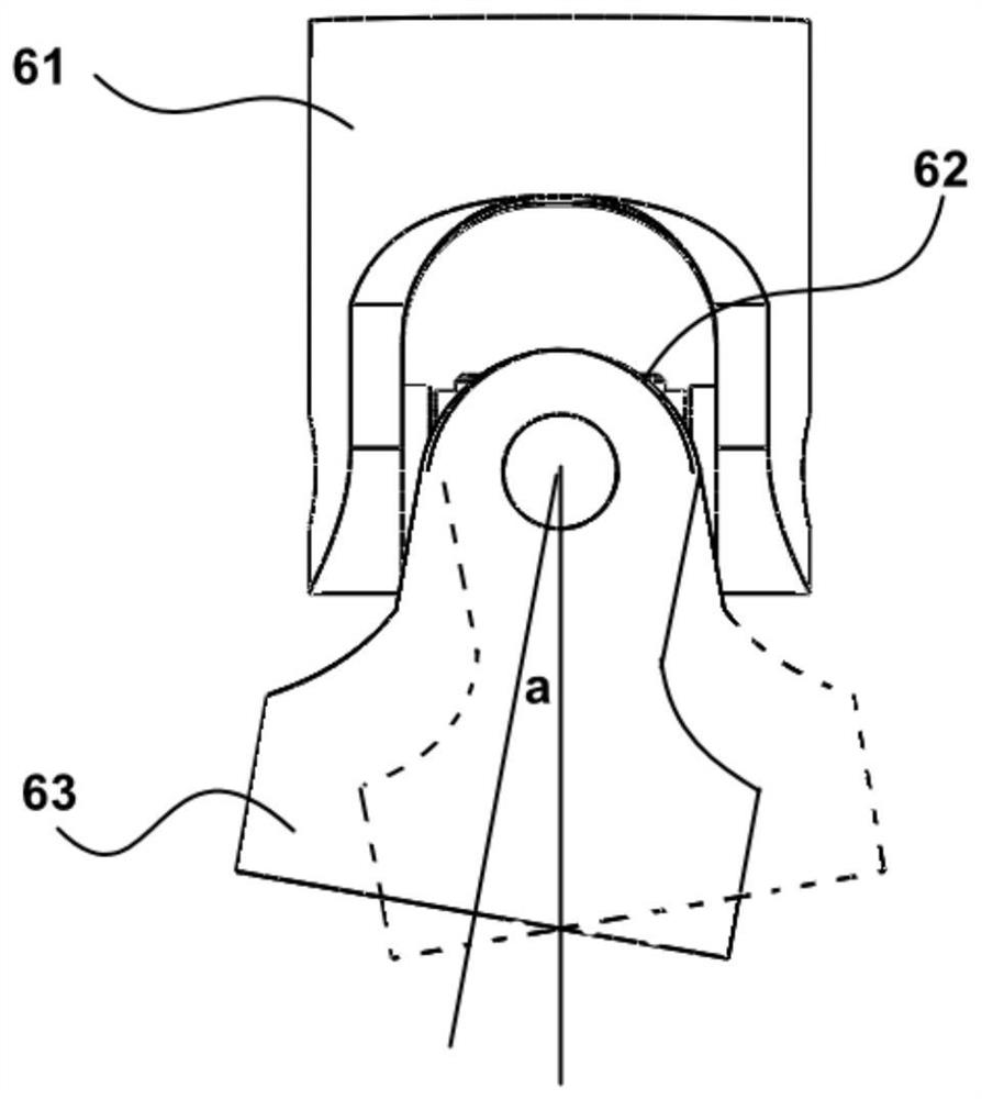
[0048] 1) The drive motor 1 is located at the top, and the grinding and polishing tool 7 is located at the bottom, and the bracket 2 of the grinding and polishing device is fixedly installed on the sixth axis flange end of the industrial robot 9 through the installation hole. The center line angle a of the input end sleeve fork 61 and the output end sleeve fork 63 is adjusted to be 0° (the deviation of the center line angle ≤ 1 ') by the limit sleeve 8. Adjust the sleeve fork 63 at the output end so that the lower surface of the grinding and polishing tool 7 is parallel to the reference plane 11-1 of the turntable (included angle≤10").

[0049] 2) The working turntable 10 is located in front of the robot 9 , and the optical element 11 to be processed is fixed on the working turntable 10 . It is stipulated that facing the industrial robot 9, the center point of the working turntable 10 is the origin, and the connection line between the industrial robot 9 and the working turntab...


PUM

PropertyMeasurementUnit
Concentricityaaaaaaaaaa

Abstract

The invention discloses an optical element grinding and polishing device and a machining method. The grinding and polishing device comprises a driving motor, a support, a coupler, a center rotating shaft, a rotating mechanism, a universal joint and a grinding and polishing tool from top to bottom. The device has the characteristics of being simple in structure, flexible to install and convenient to operate, the grinding and polishing tool makes contact with the surface of an optical element all the time in the lifting and descending process of the grinding and polishing tool, a grinding and polishing tool shaft is perpendicular to the surface of the optical element all the time, precise transmission of rotating speed loads is guaranteed, the removal amount of grinding and polishing materials of the optical element is precisely controlled, the grinding and polishing surface shape is stable, and the machining efficiency is improved.

Description

technical field [0001] The invention relates to the technical field of optical element grinding and polishing, in particular to a grinding and polishing device and a processing method for optical elements. Background technique [0002] Optical components are widely used in major national strategic needs such as laser fusion and space exploration, as well as national consumption fields such as terminal equipment, security vehicles, etc. With the development of technology and the improvement of manufacturing technology, the requirements for the processing surface accuracy of optical components are increasing. [0003] Grinding and polishing is an important part of optical component processing. CNC grinding and polishing is widely used in the field of optical manufacturing due to its advantages of certainty, high efficiency and localized removal. CNC small tool processing (CCOS) is an important means of grinding and polishing precision optical components. However, the grindin...

Claims


Application Information

Patent Timeline
Patent Type & Authority Applications(China)
IPC IPC(8): B24B13/00B24B37/00B24B37/34B24B41/04B25J11/00
CPCB24B13/00B24B37/00B24B37/34B24B41/04B25J11/0065
Inventor 顾建勋施杨余鑫巍黄伟徐浩男
Owner 恒迈光学精密机械(杭州)有限公司
Why Eureka
Try Eureka