Nanomagnetic logic multiple-selection logic gate circuit based on magnetoelectric effect clock control method

A logic gate circuit and clock control technology, applied in the direction of logic circuits with logic functions, etc., can solve the problems of NML circuit performance and reliability impact, high manufacturing process requirements, and low aspect ratio of nano-magnets, etc., to achieve easy preparation , The circuit structure is simple, the effect of improving the circuit speed

Pending Publication Date: 2022-01-21
DALIAN NEUSOFT UNIV OF INFORMATION
View PDF0 Cites 0 Cited by
  • Summary
  • Abstract
  • Description
  • Claims
  • Application Information

AI Technical Summary

Problems solved by technology

However, this solution requires a very low aspect ratio of the nanomagnet, and many characteristics of NML depend on the aspect ratio of the nanomagnet, which will affect the performance and reliability of the NML circuit.
In addition, the clock control scheme has high requirements on the manufacturing process, which is difficult to realize under the current process conditions.

Method used


Image

  • Nanomagnetic logic multiple-selection logic gate circuit based on magnetoelectric effect clock control method
  • Nanomagnetic logic multiple-selection logic gate circuit based on magnetoelectric effect clock control method
  • Nanomagnetic logic multiple-selection logic gate circuit based on magnetoelectric effect clock control method

Examples


Embodiment Construction

[0036] In order to make the purpose, technical solutions and advantages of the embodiments of the present invention clearer, the technical solutions in the embodiments of the present invention will be clearly and completely described below in conjunction with the drawings in the embodiments of the present invention. Obviously, the described embodiments It is a part of embodiments of the present invention, but not all embodiments. Based on the embodiments of the present invention, all other embodiments obtained by persons of ordinary skill in the art without creative efforts fall within the protection scope of the present invention.

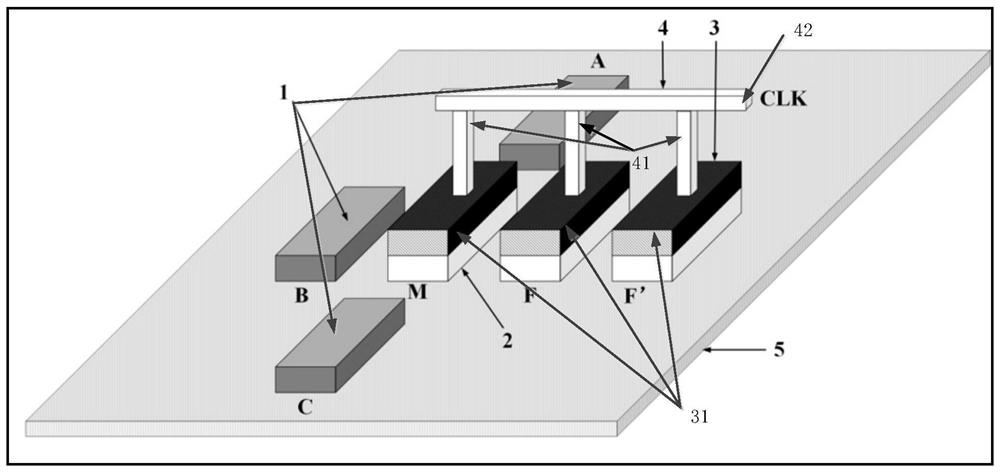
[0037] This embodiment provides a nanomagnetic logic majority logic gate circuit based on the magnetoelectric effect clock control method, as shown in the attached Figure 7 As shown, the nanomagnetic logic majority logic gate circuit includes: a first input terminal A, a second input terminal B, a third input terminal C, an input interface circui...


PUM


Abstract

The invention discloses a nano-magnetic logic multiple-selection logic gate circuit based on a magnetoelectric effect clock control method. The logic gate circuit comprises a first input end, a second input end, a third input end, an intermediate operation circuit, a first output end, a second phase inverter and a second output end, the intermediate operation circuit comprises a plurality of first phase inverters, a first two-input AND gate, a second two-input AND gate, a third two-input AND gate and a three-input OR gate. The intermediate operation circuit is connected with the input end, the output end of the intermediate operation circuit is connected with the three input OR gates, the three input OR gates are connected with the second phase inverter in series, and the output end of the second phase inverter serves as the second output end. The invention designs a clock control scheme based on a magnetoelectric effect on the basis of a majority logic gate circuit. Compared with other known clock control schemes, the clock control scheme can further reduce circuit power consumption and improve circuit speed, and the circuit is simple in structure and easy to prepare. Meanwhile, the clock control scheme is not only suitable for a majority logic gate circuit, but also can be applied to other NML circuits.

Description

technical field [0001] The invention relates to the technical field of electronic devices and circuits, in particular to a nanomagnetic logic majority logic gate circuit based on a magnetoelectric effect clock control method. Background technique [0002] Nanomagnet Logic (NML) uses single-domain nanomagnets to have two stable states to represent logic '0' and '1' respectively, and has the advantages of ultra-low power consumption, high integration and non-volatility. It is an important candidate for the post-CMOS era. In NML circuits, the majority logic gate is the basic logic unit, and the clock control scheme is an important part of the NML circuit. [0003] At present, there are three mainstream clock control schemes for NML circuits, which are clock control schemes based on current induction to generate an external magnetic field, clock control schemes based on spin transfer torque, and clock control schemes based on magnetoelastic properties. Among them, the clock co...

Claims


Application Information

Patent Timeline
Patent Type & Authority Applications(China)
IPC IPC(8): H03K19/20
CPCH03K19/20
Inventor 王森丛国涛李鹤楠山丹王晓袁
Owner DALIAN NEUSOFT UNIV OF INFORMATION
Why Eureka
Try Eureka