Cerebrovascular intervention puncture positioning system for neural intervention based on Internet

A nerve intervention and positioning system technology, applied in the field of medical devices, can solve problems such as easy shaking of catheters and separate connections of catheters, and achieve the effects of shortening operation time, reducing difficulty in positioning, and reducing measurement

Pending Publication Date: 2022-01-28
孙蕾蕾
View PDF0 Cites 0 Cited by
  • Summary
  • Abstract
  • Description
  • Claims
  • Application Information

AI Technical Summary

Problems solved by technology

[0004] The purpose of the present invention is to solve the problems of the accuracy of puncture positioning, separate connection of puncture needle and catheter, and easy shaking of the catheter in the prior art, and propose a compact Internet-based cerebrovascular interventional puncture positioning system for neurological intervention

Method used


Image

  • Cerebrovascular intervention puncture positioning system for neural intervention based on Internet
  • Cerebrovascular intervention puncture positioning system for neural intervention based on Internet
  • Cerebrovascular intervention puncture positioning system for neural intervention based on Internet

Examples


Embodiment 1

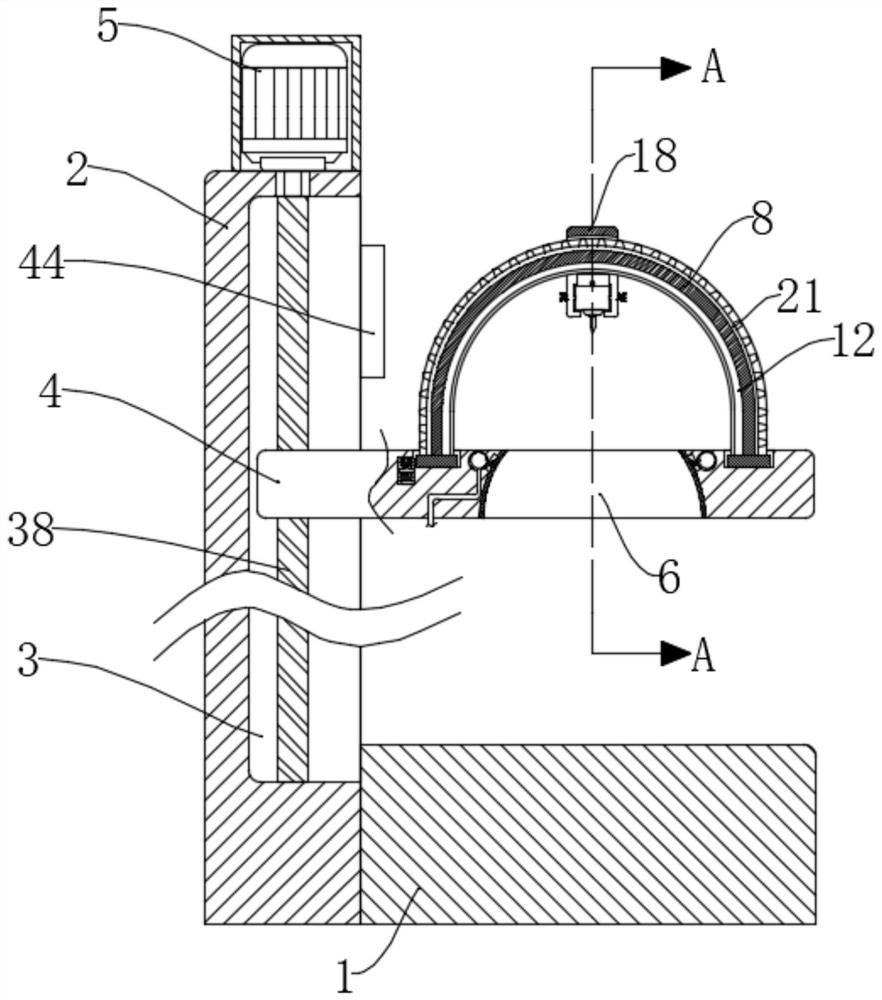
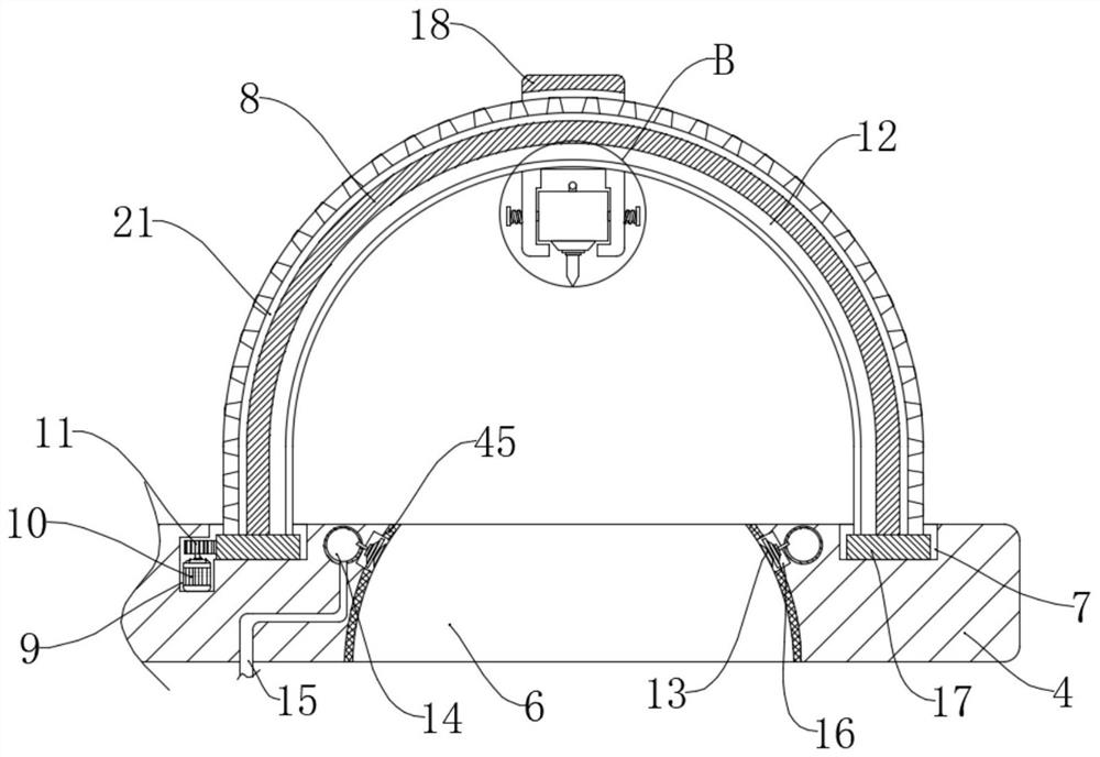
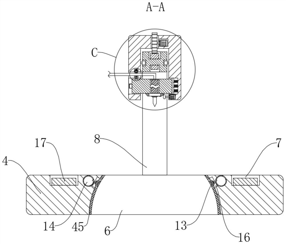
[0038] refer to Figure 1-10 , an Internet-based cerebrovascular interventional puncture positioning system for nerve intervention, including a seat 1 and a catheter 37, one side of the seat 1 is fixedly connected with a support plate 2 by bolts, and the side of the support plate 2 close to the seat 1 is provided with a rectangular Slot 3, in the rectangular slot 3, there is a threaded mandrel 38 connected to the longitudinal rotation, the top of the support plate 2 is fixedly connected with a rotating motor 5 by bolts, and the output shaft of the rotating motor 5 rotates through the inner wall of the top of the rectangular slot 3 and passes through the shaft coupling and The screw rod 38 is fixedly connected, the horizontal plate 4 is slidably connected in the rectangular groove 3, and the bottom end of the screw rod 38 is threaded through the horizontal plate 4, the horizontal plate 4 is provided with a groove 6, and the inner wall of the groove 6 is fixedly connected with a ...

Embodiment 2

[0045] refer to Figure 1-12 , an Internet-based cerebrovascular interventional puncture positioning system for nerve intervention, including a seat 1 and a catheter 37, one side of the seat 1 is fixedly connected with a support plate 2 by bolts, and the side of the support plate 2 close to the seat 1 is provided with a rectangular Slot 3, in the rectangular slot 3, there is a threaded mandrel 38 connected to the longitudinal rotation, the top of the support plate 2 is fixedly connected with a rotating motor 5 by bolts, and the output shaft of the rotating motor 5 rotates through the inner wall of the top of the rectangular slot 3 and passes through the shaft coupling and The screw rod 38 is fixedly connected, the horizontal plate 4 is slidably connected in the rectangular groove 3, and the bottom end of the screw rod 38 is threaded through the horizontal plate 4, the horizontal plate 4 is provided with a groove 6, and the inner wall of the groove 6 is fixedly connected with a ...


PUM


Abstract

The invention relates to a cerebrovascular intervention puncture positioning system for neural intervention based on Internet, which comprises a seat and a catheter, a supporting plate is fixedly connected to one side of the seat, a rectangular groove is formed in the side, close to the seat, of the supporting plate, and a screw rod is longitudinally and rotationally connected into the rectangular groove; the top end of the supporting plate is fixedly connected with a rotating motor, and an output shaft of the rotating motor rotationally penetrates through the inner wall of the top of the rectangular groove and is fixedly connected with the lead screw.The system has a simple structure, scans the patient's head data through a scanner, and transmits the data to the Internet through a control panel, so as to quickly calculate the optimal puncture position, the driving motor and a first small motor are sequentially started through the control panel to accurately and quickly move the puncture needle to the optimal puncture position, and when the puncture needle is clamped before puncture, the catheter can be connected with the puncture needle in advance, so that the workload of a doctor is reduced, and the operation time is shortened.

Description

technical field [0001] The invention relates to the technical field of medical devices, in particular to an Internet-based cerebrovascular intervention puncture positioning system for nerve intervention. Background technique [0002] Cardiovascular and cerebrovascular diseases are collectively referred to as cardiovascular and cerebrovascular diseases. disease. [0003] In the prior art, when performing cardiovascular and cerebrovascular interventional treatment for patients, most of the puncture needles are used to directly puncture the blood vessels, and then the syringe is removed, and then the guide wire is inserted. It is easy to position and puncture the blood vessel to be punctured, which not only has extremely high requirements on the doctor’s experience and control ability, but also easily leads to inaccurate puncture position and poses a safety hazard. After the puncture is completed, the syringe needs to be removed and connected Catheters and guide wires, this p...

Claims


Application Information

Patent Timeline
Patent Type & Authority Applications(China)
IPC IPC(8): A61B17/34A61M35/00
CPCA61B17/3403A61M35/20A61B2017/3407A61B2017/3409
Inventor 孙蕾蕾
Owner 孙蕾蕾
Why Eureka
Try Eureka