
Anesthesiology department adjustable positioning anesthetic needle

An anesthesia needle and adjustable technology, applied in the field of anesthesiology, can solve the problems of insufficient rigor and low precision, and achieve the effects of easy replacement, high safety and simple operation

Pending Publication Date: 2022-01-28
高鹏
View PDF15 Cites 0 Cited by
  • Summary
  • Abstract
  • Description
  • Claims
  • Application Information

AI Technical Summary

Problems solved by technology

[0005] The purpose of the present invention is to provide an anesthesia needle with adjustable positioning in the department of anesthesiology to solve the problem that the way of determining the puncture site through visual inspection and manual inspection proposed in the above background technology is not rigorous enough and has low accuracy

Method used


Image

  • Anesthesiology department adjustable positioning anesthetic needle
  • Anesthesiology department adjustable positioning anesthetic needle
  • Anesthesiology department adjustable positioning anesthetic needle

Examples


Embodiment 1

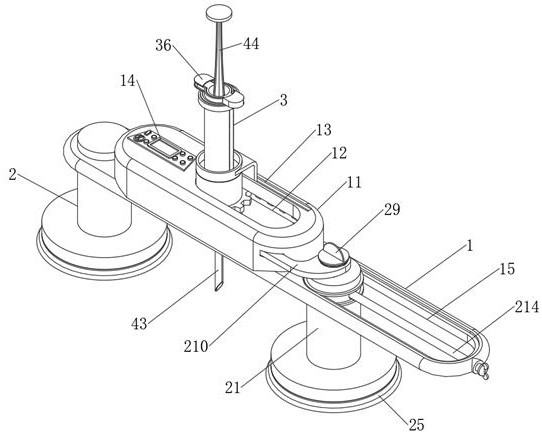
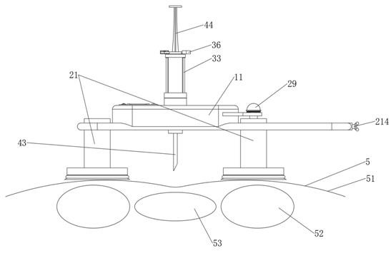
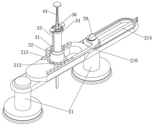
[0026] see Figure 1-8 , an embodiment provided by the present invention: an anesthesia needle with adjustable positioning in the department of anesthesiology, comprising:

[0027] The anesthesia needle body 1, the anesthesia needle body 1 includes a housing 11, the inner side of the housing 11 is provided with a movable chamber 12, the top surface of the housing 11 is provided with a chute 13, and a controller 14 is fixedly installed on one side of the chute 13, The right end of the top surface of the housing 11 is provided with a movable groove 15;

[0028] Adjust the positioning structure 2, the adjusting positioning structure 2 includes a fixed column 21, the fixed column 21 is slidably installed inside the movable groove 15, the bottom surface of the fixed column 21 is fixedly installed with a female sticker 22, and the center of the bottom surface of the fixed column 21 is provided with a guide groove 23, The lower side of the mother patch 22 is equipped with a sub-stic...

Embodiment 2

[0040] When in use, assist the patient’s waist to bend backwards, the vertebrae 52 will push up the human skin 51 to form two protrusions, fit the bottom of the left set of fixed columns 21 to the protrusions, and rotate the handle 214, The handle bar 214 drives one group of fixed columns 21 to translate inside the movable groove 15, so that the two groups of fixed columns 21 are far away, and ensure that the other group of fixed columns 21 fits with the other raised part, and then the two groups of sub-sticks 24 are placed on the Two sets of female stickers 22 fit together, put the needle cylinder 41 into the storage tube 39, make the cylinder ear 42 inside the ear groove 311, and rotate the overcoat 36, the overcoat 36 can cover the fixed block 310 and the cylinder ear 42, and pull The insertion rod 29 and the connecting rod 210, while the connecting rod 210 drives the gear 212 to rotate, the gear 212 meshes with the rack plate 213, rotates and moves inside the movable chambe...


PUM


Abstract

The invention relates to the technical field of anesthesiology department, in particular to an anesthesiology department adjustable positioning anesthetic needle which comprises an anesthetic needle body, the anesthetic needle body comprises a shell, a movable cavity is formed in the inner side of the shell, a sliding groove is formed in the top face of the shell, a controller is fixedly installed on one side of the sliding groove, a movable groove is formed in the right end of the top surface of the shell; the adjusting and positioning structure comprises a fixing column, the fixing column is slidably installed in the movable groove, and a female sticker is fixedly installed on the bottom face of the fixing column. According to the anesthetic needle, the distance between the two fixing columns can be adjusted by rotating the hand lever to adapt to people with different physiques, the gear can be driven to slide in the movable cavity by pulling the connecting rod, the needle cylinder on the inner side of the gear is located over the centers of the two adjacent vertebrae, the puncture position of the needle head can be accurately determined, operation is easy, and the safety is high.

Description

technical field [0001] The invention relates to the technical field of anesthesiology, in particular to an adjustable positioning anesthesia needle for anesthesiology. Background technique [0002] Anesthesiology is a comprehensive discipline, which contains multidisciplinary knowledge. The scope is very wide, not only to meet the requirements of surgery, but also to participate in the rescue work of various departments, painless childbirth in gynecology, painless abortion and so on. [0003] When anesthesia needles are used for painless childbirth, most of them use intraspinal anesthesia, and the drug needs to be injected into the subarachnoid space. During the operation, the patient needs to keep the side lying position and bend the waist backward, curling up like a shrimp. The vertebrae will push up the skin, exposing the entire spine, and then the surgeon will determine the puncture by observing the two adjacent groups of raised parts, and using visual and manual measur...

Claims


Application Information

Patent Timeline
Patent Type & Authority Applications(China)
IPC IPC(8): A61B17/34
CPCA61B17/3401A61B17/3403A61B2017/3409
Inventor 高鹏
Owner 高鹏
Learn More