Positioning and guiding ablation probe

A positioning guide and probe technology, applied in the field of biomedical engineering, can solve problems such as increasing the difficulty of the doctor's operation, incomplete ablation, and inability to achieve therapeutic effects, and achieves the goal of reducing puncture time, improving ablation efficiency and treatment rate, and reducing difficulty. Effect

Pending Publication Date: 2022-01-28
SHANGHAI JIAO TONG UNIV
View PDF0 Cites 0 Cited by
  • Summary
  • Abstract
  • Description
  • Claims
  • Application Information

AI Technical Summary

Problems solved by technology

Existing minimally invasive ablation methods mainly use percutaneous puncture to enter the target tissue. Doctors will be limited by conditions such as bones and organs at the puncture site during operation, and cannot grasp the patient's body characteristics well, especially those who cannot The skin puncture site, which further increases the difficulty of the doctor's operation, making it difficult for the doctor to insert the puncture and ablation probe into the most ideal position for the doctor's evaluation
In addition, most of the ablated tissues are irregular, which increases the difficulty of ablation, which may cause incomplete ablation and fail to achieve the best expected therapeutic effect.

Method used


Image

  • Positioning and guiding ablation probe
  • Positioning and guiding ablation probe
  • Positioning and guiding ablation probe

Examples


Embodiment Construction

[0027] The terms "invention", "present invention" and "present invention" as used in this specification are intended to refer broadly to all subject matter of any patent claims that follow in this specification. Statements containing these terms should not be read to limit the subject matter described herein or to limit the meaning or scope of any patent claims below. Furthermore, this specification is not intended to describe or limit the subject matter encompassed by any claim of any particular element, paragraph, statement, or drawing of the application. The subject matter should be understood by reference to the entire specification, all drawings and any claims that follow. The invention is capable of other embodiments and of being practiced or carried out in other ways. Also, it is to be understood that the phraseology and terminology employed herein are for the purpose of description and should not be regarded as limiting.

[0028] Details of the invention will now be ...


PUM


Abstract

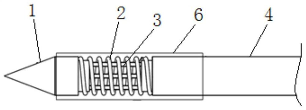
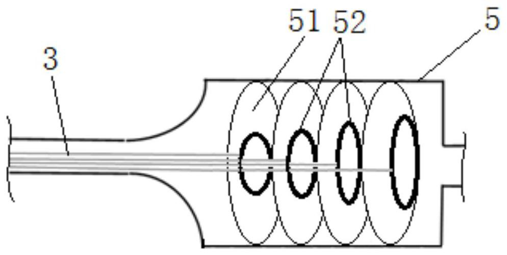
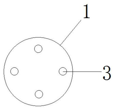
The invention discloses a positioning and guiding ablation probe which comprises an ablation probe body. The ablation probe body comprises a guide puncture probe, a bourdon tube, a guide connecting piece, a guide rod, a guide control device and ablation electrodes. The guide puncture probe, the bourdon tube and the guide rod are sequentially connected. The guide connecting piece is arranged in the bourdon tube. The guide control device adjusts the puncture path of the guide puncture probe through the guide connecting piece and controls the elastic strain of the bourdon tube to adjust the puncture force of the probe. The ablation electrodes are evenly distributed on the peripheral sides of the bourdon tube and the guide rod. According to the positioning and guiding ablation probe, the puncture path of a puncture ablation needle can be controlled to deflect under the condition that puncture force is guaranteed, so that the puncture ablation needle can accurately reach an expected target puncture position; and a therapeutic electrode can be selected according to the form of the ablation tissue, and the purpose of more thorough and conformal treatment is achieved. According to the invention, the difficulty of a puncture operation of a doctor is reduced, the puncture time is shortened, the ablation efficiency and the treatment rate are improved, and meanwhile, the popularization of a minimally invasive ablation technology is also facilitated.

Description

technical field [0001] The invention belongs to the technical field of biomedical engineering, and in particular relates to a positioning-guided ablation probe. Background technique [0002] With the development of science and technology, especially the advancement of medical imaging technologies such as nuclear magnetic resonance imaging and ultrasound imaging, minimally invasive treatments such as radiofrequency ablation, microwave ablation, and nanoknife have made great progress. Existing minimally invasive ablation methods mainly use percutaneous puncture to enter the target tissue. Doctors will be limited by conditions such as bones and organs at the puncture site during operation, and cannot grasp the patient's body characteristics well, especially those who cannot This further increases the difficulty of the doctor's operation, making it difficult for the doctor to insert the puncture and ablation probe into the most ideal position for the doctor's evaluation. In add...

Claims


Application Information

Patent Timeline
Patent Type & Authority Applications(China)
IPC IPC(8): A61B18/02A61B18/12A61B18/14A61B18/18A61B17/34
CPCA61B18/02A61B18/12A61B18/1402A61B18/1815A61B17/3403A61B17/3476A61B2018/0293A61B2018/1467A61B2018/1869
Inventor 邹金成张爱丽
Owner SHANGHAI JIAO TONG UNIV
Why Eureka
Try Eureka