Feeding device for electric coating production

A feeding device and coating technology, applied in solid separation, chemical instruments and methods, grain processing, etc., can solve problems such as accumulation, troublesome cleaning work, and inability to break large particles of materials, and achieve the effect of avoiding waste

Active Publication Date: 2022-01-28
澳昌(武汉)生态科技有限公司
View PDF6 Cites 1 Cited by
  • Summary
  • Abstract
  • Description
  • Claims
  • Application Information

AI Technical Summary

Problems solved by technology

[0003]The feeding device on the existing power coating production equipment cannot help the production equipment to filter out the large particles that are not easy to mix when conveying materials, so these materials cannot be mixed in the solvent It is easy to accumulate inside the production equipment, which brings troubles to the subsequent cleaning work, and the existing feeding device cannot crush the large particle materials that are difficult to dissolve and mix, which easily leads to waste of materials

Method used


Image

  • Feeding device for electric coating production
  • Feeding device for electric coating production
  • Feeding device for electric coating production

Examples


Embodiment 1

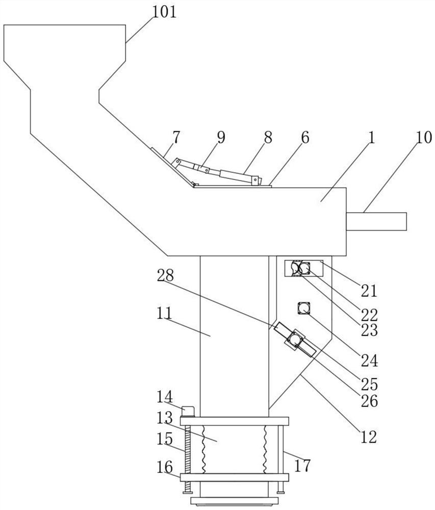
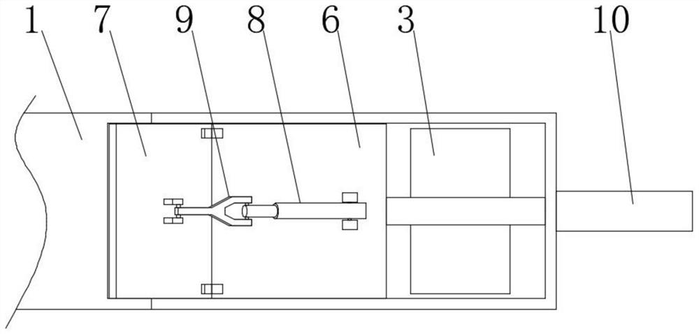
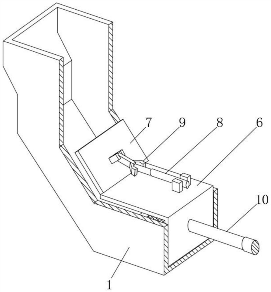
[0028] As shown in the drawings, the embodiment of the present invention provides a feeding device for the production of electric paint, including a feeding channel 1, the top of the feeding channel 1 is provided with a feeding port 101, and the bottom end of the feeding channel 1 is far away from the feeding port One side of 101 is evenly provided with two material guide ports 3, and the inner side of one of the material guide ports 3 is provided with a screen 2, and the edge of the screen 2 is fixedly connected with the inner wall of the material guide port 3 with an elastic leather sheath 5. A vibrating motor 4 is fixedly connected to the bottom of the screen 2, a pushing assembly is arranged on the top side of the screen 2, and a first material guide pipe 11 and a second guide tube 11 are fixedly connected to the bottom ends of the two material guide ports 3 respectively. The feed pipe 12, and the second feed pipe 12 and the first feed pipe 11 are connected to each other, t...

Embodiment 2

[0036] The structure of this embodiment is basically the same as that of Embodiment 1, the difference is that:

[0037] Specifically, the bottom end of the first material guide pipe 11 is fixedly connected with a telescopic cover 13, the bottom end of the telescopic cover 13 is fixedly connected with a butt joint 16, and the bottom side of the first material guide tube 11 is fixedly connected with a drive motor 14, and the drive motor The output end of 14 is fixedly connected with an adjusting screw 15, which is threadedly connected with the butt joint 16, so that the adjustment screw 15 drives the butt joint 16 to move down through the drive of the drive motor 14 until the butt joint 16 and the production equipment enter The material end is butted, so as to prevent the material from splashing out from between the first material guide pipe 11 and the feeding end of the production equipment when it falls into the production equipment.

[0038] Specifically, the side of the butt...


PUM


Abstract

The invention provides a feeding device for electric coating production, and relates to the technical field of coating production. The feeding device for electric coating production comprises a material conveying channel, a material inlet is formed in the top end of the material conveying channel, two material guiding openings are evenly formed in the side, away from the material inlet, of the bottom end of the material conveying channel, and a screen is arranged on the inner side of one material guiding opening. A first hydraulic push rod pushes a connecting frame to enable a rotating plate to rotate downwards and abut against the side wall of a limiting frame, then a second hydraulic push rod pulls the limiting frame, large-particle materials of the rotating plate are pushed into a second material guide pipe, and the situation that the large-particle materials stop small-particle materials from falling into the inner side of production equipment is avoided; and large-particle materials are ground through the first grinding roller and the second grinding roller so that the materials can be dissolved more rapidly, then the ground materials are guided into the inner side of the first material guide pipe and finally fall into production equipment, recycling of the large-particle materials is achieved, and waste of the materials is avoided.

Description

technical field [0001] The invention relates to the technical field of paint production, in particular to a feeding device for electric paint production. Background technique [0002] Coating refers to a type of liquid or solid material that can form a thin film on the surface of an object under certain conditions for protection, decoration or other special functions (insulation, rust prevention, mildew resistance, heat resistance, etc.). [0003] The feeding device on the existing electric paint production equipment cannot help the production equipment to filter out the large particle materials that are not easy to mix when conveying materials, so these materials cannot be mixed in the solvent and are easy to accumulate inside the production equipment, so as to be used later. The cleaning work brings trouble, and the existing feeding device cannot crush the large-grained materials that are difficult to dissolve and mix, which easily leads to waste of materials. Contents o...

Claims


Application Information

Patent Timeline
Patent Type & Authority Applications(China)
IPC IPC(8): B02C4/08B02C4/20B02C4/30B02C21/00B02C23/08B07B1/28B07B1/52
CPCB02C4/08B02C4/20B02C4/30B02C21/00B02C23/08B07B1/28B07B1/526
Inventor 刘倩童飞
Owner 澳昌(武汉)生态科技有限公司
Why Eureka
Try Eureka