Copper bar bending die head

A bending die and bending technology, used in forming tools, manufacturing tools, metal processing equipment, etc., can solve the problems of easy deviation, easy accumulation of dust in the mold, single structure, etc., to prevent moisture and rust, and to prevent moisture protective effect

Inactive Publication Date: 2022-01-28
贵溪金河铜业有限公司
View PDF0 Cites 0 Cited by
  • Summary
  • Abstract
  • Description
  • Claims
  • Application Information

AI Technical Summary

Problems solved by technology

[0003] Most of the existing copper bar bending punches and stamping dies have a single structure and can only bend one form. When bending other forms, it is often necessary to disassemble the unused stamping head and stamping die , and then install the stamping head and stamping die to be used on the stamping and bending device. In this way, it is more troublesome to change the bending die and bending punching head, the replacement speed is slower, and the installation is more troublesome, and the unused mold and Most of the bending punches are placed on the storage rack when not in use. After a long time, the mold is easy to accumulate dust, and it is also easily affected by the moisture in the air. When the mold is in use, it is more troublesome to install. There is no fixed structure when bending. The bending position of the copper bar is easy to shift when bending. For this reason, we propose a copper bar bending die head

Method used


Image

  • Copper bar bending die head
  • Copper bar bending die head
  • Copper bar bending die head

Examples


Embodiment Construction

[0026] The following will clearly and completely describe the technical solutions in the embodiments of the present invention with reference to the accompanying drawings in the embodiments of the present invention. Obviously, the described embodiments are only some, not all, embodiments of the present invention. Based on the embodiments of the present invention, all other embodiments obtained by persons of ordinary skill in the art without making creative efforts belong to the protection scope of the present invention.

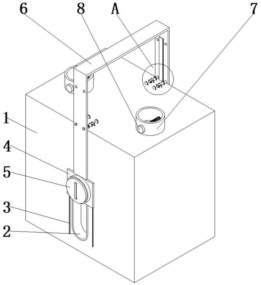
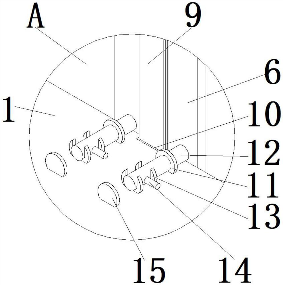
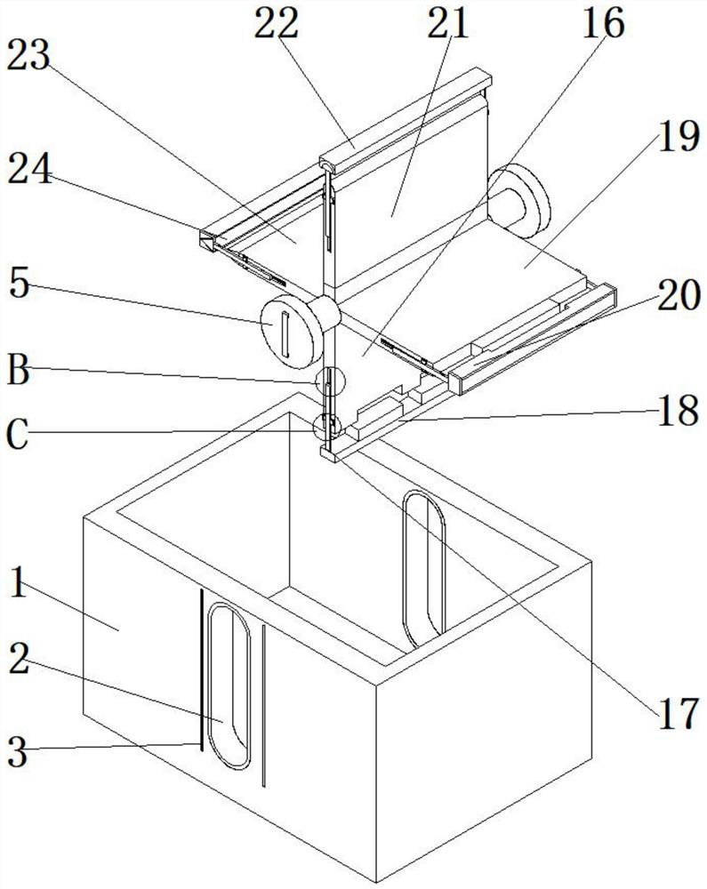
[0027] see Figure 1-9 , the present invention provides a technical solution: a copper bar bending die head, including a main body protection box 1, the middle part of one side of the main body protection box 1 is fixedly connected with a lifting cavity 2, and the top of one side of the lifting cavity 2 is slidably connected with a card Hoop plate 4, one end on one side of the hoop plate 4 is fixedly connected with a first stopper 37, the outer side of the fir...


PUM


Abstract

The invention discloses a copper bar bending die head. The copper bar bending die head comprises a main body protection box, wherein a lifting cavity is fixedly connected to the middle of one side of the main body protection box; a clamping plate is slidably connected to the top end of one side of the lifting cavity; a first limiting block is fixedly connected to one end of one side of the clamping plate; a first limiting groove is slidably connected to an outer side of the first limiting block; a limiting sliding rod is slidably connected to the middle of an inner side of the first limiting block; a limiting rotating rod is arranged in the middle of an inner side of the clamping plate; and an adjusting pull frame is fixedly connected to the middle of the top end of the clamping plate. The invention has the beneficial effects that it is convenient to replace a die, and die replacement is convenient; compared with a mode in which an unused die is disassembled and then a needed die is installed on a stamping device, the invention is rapid, time-saving and labor-saving; clamping and bending of a copper bar are facilitated, and during bending, the copper bar can be prevented from deviating; and damp-proof protection can be conveniently conducted on the unused die, and the die can be prevented from being affected with damp and rusting.

Description

technical field [0001] The invention belongs to the technical field of copper bar processing, and in particular relates to a copper bar bending die head. Background technique [0002] Copper is a metal element and a transition element. Pure copper is a soft metal. The surface is reddish orange with metallic luster when it is just cut, and the single substance is purplish red. Good ductility, high thermal conductivity and electrical conductivity, so it is the most commonly used material in cables and electrical and electronic components. It can also be used as a building material and can form many kinds of alloys. Copper has been mined and utilized very early in Chinese history. , Copper is an indispensable metal in today's society. Copper is used in many electrical appliances and machines, especially copper bars. In order to meet the processing of copper bars, it needs to be bent, so many factories have introduced copper bar bending. bend components. [0003] Most of the e...

Claims


Application Information

Patent Timeline
Patent Type & Authority Applications(China)
IPC IPC(8): B21D5/02B21D37/04B21D55/00
CPCB21D5/0254B21D37/04B21D55/00
Inventor 金炳泰
Owner 贵溪金河铜业有限公司
Why Eureka
Try Eureka