Continuous welding device for laser hybrid welding

A composite welding and welding device technology, which is applied to laser welding equipment, welding equipment, metal processing equipment, etc., can solve the problems of inability to align and skew two metal plates, and achieve the effect of convenient continuous welding and high efficiency

Inactive Publication Date: 2022-01-28
LANDAHE INTELLIGENT EQUIP (SUZHOU) CO LTD
View PDF0 Cites 2 Cited by
  • Summary
  • Abstract
  • Description
  • Claims
  • Application Information

AI Technical Summary

Problems solved by technology

[0005] In order to overcome the above-mentioned defects of the prior art, an embodiment of the present invention provides a continuous welding device for laser hybrid welding. The technical problem to be solved by the present invention is: the vertical welding of two metal plates is usually a manual operation, which cannot be well welded. Alignment of two metal plates may cause irreparable problems such as skew

Method used


Image

  • Continuous welding device for laser hybrid welding
  • Continuous welding device for laser hybrid welding
  • Continuous welding device for laser hybrid welding

Examples


Embodiment 1

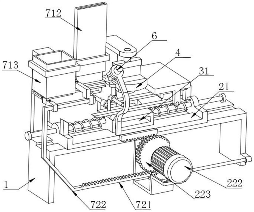
[0035] like Figure 1-9 As shown, a continuous welding device for laser hybrid welding is used for welding metal plate 1 100 and metal plate 2 200 placed perpendicularly to each other, such as Figure 5 As shown, the metal plate 100 is placed horizontally, and the metal plate 200 is vertically placed in the middle of the metal plate 100, and the two sides of the contact position need to be welded, that is, weld A and weld B;

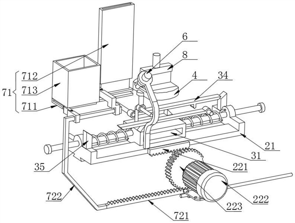
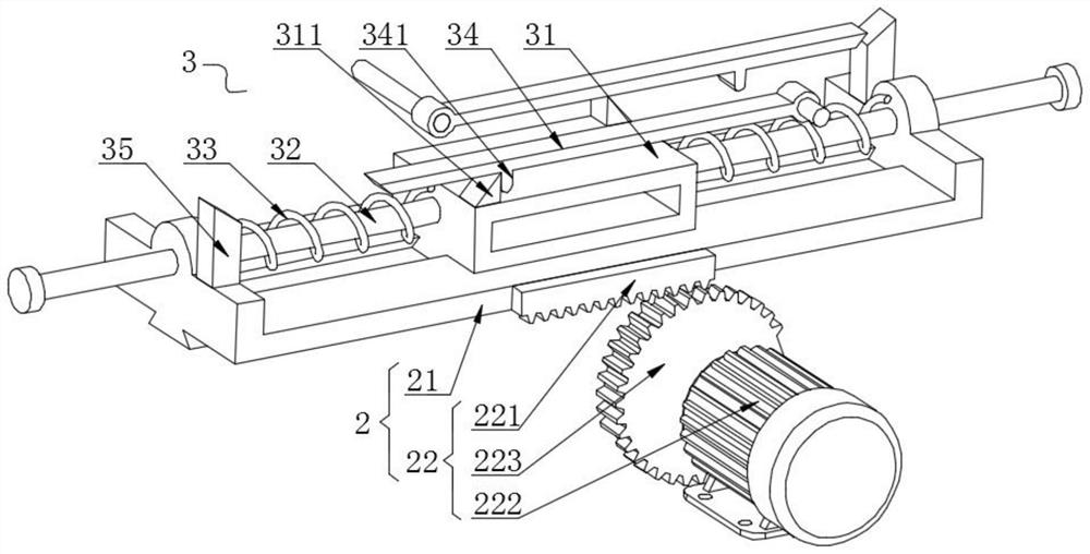
[0036] The welding device includes a frame 1 and a power assembly 2. The power assembly 2 includes a sliding table 21 that slides on the frame 1 and a driving mechanism 22 that drives the sliding table 21 to reciprocate. The sliding table 21 and the frame 1 can use dovetail grooves, etc. Connection, specifically, the driving mechanism 22 includes a rack one 221 fixedly connected with the slide table 21, a driving device 222 installed on the frame 1, a gear 223 connected with the output shaft of the driving mechanism 22, and the gear 223 is connected with...

Embodiment 2

[0046] like Figure 1-2 and Figure 6-8 As shown, on the basis of the first embodiment, the feeding mechanism 7 can be added to automatically feed the first metal plate 100 and the second metal plate 200. Specifically, the feeding mechanism 7 includes a loading mechanism 71, and the loading mechanism 71 includes a The frame 1 is fixedly connected and arranged on the slot plate 711 on one side of the welding table 4, the first barrel 712 and the second barrel 713 that are fixedly connected to the frame 1 above the slot plate 711, and the first barrel 712 is located on the welding table 4. Between the barrel two 713, the inner sides of the barrel one 712 and the barrel two 713 are used to place the metal plate two 200 and the metal plate one 100 respectively, and the metal plate two 200 inside the barrel one 712 can be dropped On the upper surface of the groove plate 711, the metal plate one 100 inside the barrel two 713 can fall on the inner side of the groove plate 711.

[0...


PUM


Abstract

The invention discloses a continuous welding device for laser hybrid welding, wherein the device is used for welding a metal plate I and a metal plate II which are mutually vertically arranged; and the invention particularly relates to the technical field of welding. The continuous welding device comprises a rack and a power assembly, and the power assembly comprises a sliding table sliding on the rack and a driving mechanism driving the sliding table to move in a reciprocating manner; the continuous welding device also comprises a rapid punching assembly arranged on the sliding table, the rapid punching assembly comprises a rapid punching table capable of sliding on the sliding table, and the sliding table can move in a reciprocating mode to drive the rapid punching table to advance; and the continuous welding device further comprises a welding table, the rapid punching table can drive the welding table to rotate when moving, and a welding gun used for welding the metal plate I and the metal plate II is fixedly mounted on the sliding table. On one hand, a welding seam A and a welding seam B are welded in sequence through left-right movement of the sliding table, and on the other hand, the positions can be switched after first-time welding, so that continuous welding and continuous welding are facilitated, and the efficiency is high.

Description

technical field [0001] The invention relates to the field of welding technology, more specifically, the invention relates to a continuous welding device for laser hybrid welding. Background technique [0002] Laser welding is a more efficient welding method at present. Its principle is to melt the workpiece to form a specific molten pool. When two metal plates are welded vertically, the two sides that are in contact with each other need to be welded. The seams need to be welded one by one, otherwise the stress will increase significantly. [0003] At present, the vertical welding of two metal plates is usually a manual operation, which cannot align the two metal plates well, which may cause irreparable problems such as skew. [0004] The above information disclosed in this Background section is only for enhancement of understanding of the background of the disclosure and therefore it may contain information that does not form the prior art that is already known in the art t...

Claims


Application Information

Patent Timeline
Patent Type & Authority Applications(China)
IPC IPC(8): B23K26/24B23K26/70
CPCB23K26/24B23K26/702
Inventor 符春红许飞李侠唐建波徐志萍
Owner LANDAHE INTELLIGENT EQUIP (SUZHOU) CO LTD
Why Eureka
Try Eureka