Linear sliding device
A technology of linear sliding and sliding direction, which is applied in the direction of large fixed members, metal processing machinery parts, maintenance and safety accessories, etc. It can solve the problems that the fluid lubrication state cannot be formed and the frictional resistance cannot be effectively reduced, so as to improve the crawling problem and increase the Wide range of application, the effect of reducing energy consumption
- Summary
- Abstract
- Description
- Claims
- Application Information
AI Technical Summary
Problems solved by technology
Method used
Image
Examples
Embodiment 1
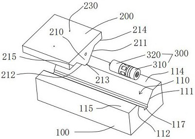
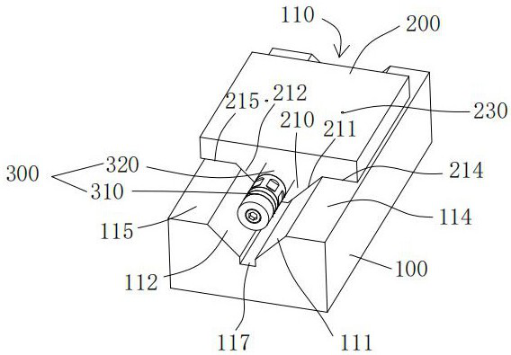
[0036] A linear slide device such as figure 1 and figure 2 As shown, it includes: a first guide rail 100 , a second guide rail 200 and an ultrasonic vibrator 300 . The first guide rail 100 is provided with a first groove 110; the second guide rail 200 is provided with a first boss 210; the first boss 210 is accommodated in the first groove 110, and the first boss 210 can be opposite to the first groove 110 Sliding, lubricant is contained between the first boss 210 and the first groove 110 . The ultrasonic vibrator 300 is fixedly connected to the second guide rail 200 , and in this embodiment, the axial direction of the ultrasonic vibrator 300 is parallel to the sliding direction of the first boss 210 .
[0037] The vibration of the ultrasonic vibrator 300 drives the first boss 210 to vibrate at a high frequency and low amplitude. Through the same high-frequency vibration as the sliding direction, the lubricant moves rapidly along the sliding direction and enters the sliding...
Embodiment 2
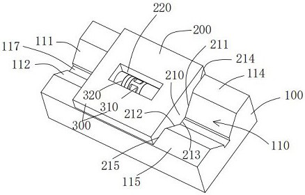
[0048] The content of this embodiment is the same as that of Embodiment 1 and will not be repeated. The difference is that: image 3 As shown, the side of the second guide rail 200 away from the first boss 210 is provided with a second groove 220 , and the second groove 220 accommodates the ultrasonic vibrator 300 . The ultrasonic vibrator 300 is not outside, further freeing up space. The above settings can also be set in other embodiments, and the scope of protection of the present invention includes but is not limited to the situations enumerated in this embodiment.
Embodiment 3
[0050] The content of this embodiment is the same as that of Embodiment 2 and will not be repeated. The difference is that: Figure 4 As shown, the side of the second guide rail 200 away from the first boss 210 is provided with a second groove 220 , and the second groove 220 has an open port on one side. The setting of the open port reduces the processing difficulty, and the processing can be directly carried out from the open port, and also reduces the installation difficulty of the ultrasonic vibrator 300, and the ultrasonic vibrator 300 can be directly plugged and installed from the open port to the inside. The above settings can also be set in other embodiments, and the scope of protection of the present invention includes but is not limited to the situations enumerated in this embodiment.
PUM
 Abstract
Description
Claims
Application Information
 - R&D
- Intellectual Property
- Life Sciences
- Materials
- Tech Scout
- Unparalleled Data Quality
- Higher Quality Content
- 60% Fewer Hallucinations
Browse by: Latest US Patents, China's latest patents, Technical Efficacy Thesaurus, Application Domain, Technology Topic, Popular Technical Reports.
© 2025 PatSnap. All rights reserved.Legal|Privacy policy|Modern Slavery Act Transparency Statement|Sitemap|About US| Contact US: help@patsnap.com


