
Tunnel non-motorized vehicle lane groove cover plate mounting device

A non-motorized vehicle lane and installation device technology, which is applied in the direction of lifting equipment braking device, hoisting device, hoisting device, etc., can solve the problem of high labor intensity of construction personnel, difficulty in ensuring construction progress, safety and installation quality, construction personnel injury, etc. It can avoid the instability of left and right swing, solve the problem of frequent movement, and ensure the quality of installation.

Pending Publication Date: 2022-01-28
浙江省建投交通基础建设集团有限公司
View PDF11 Cites 0 Cited by
  • Summary
  • Abstract
  • Description
  • Claims
  • Application Information

AI Technical Summary

Problems solved by technology

The non-motorway trench cover plate is large in size and heavy in weight, with a weight of 107~312kg. A cover plate needs 2-4 people to lift and install it. It is difficult to install, the construction progress is slow, and the labor intensity of the construction personnel is high. Machinery such as loaders is used. The hoisting will reduce the efficiency of the equipment, affect the passage of vehicles in the tunnel, and easily cause mechanical damage. During the construction process, it is easy to cause injuries to the construction personnel, and the collision during the movement of the cover plate will cause missing corners and blocks.
[0003] In order to ensure construction safety, progress and installation quality, conventional cover plate installation is carried out by manpower, which is difficult to guarantee the construction progress, safety and installation quality, and there are great safety hazards in mechanical installation

Method used


Image

  • Tunnel non-motorized vehicle lane groove cover plate mounting device
  • Tunnel non-motorized vehicle lane groove cover plate mounting device
  • Tunnel non-motorized vehicle lane groove cover plate mounting device

Examples


Embodiment Construction

[0024] The following will clearly and completely describe the technical solutions in the embodiments of the present invention with reference to the accompanying drawings in the embodiments of the present invention. Obviously, the described embodiments are only some, not all, embodiments of the present invention. Based on the embodiments of the present invention, all other embodiments obtained by persons of ordinary skill in the art without making creative efforts belong to the protection scope of the present invention.

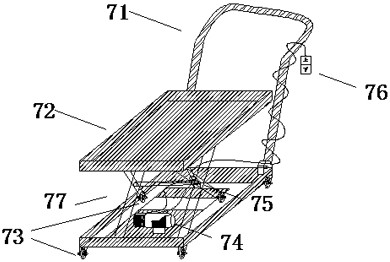
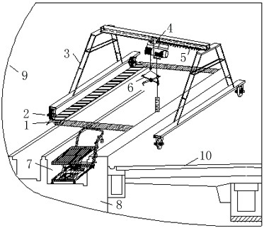
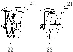
[0025] like Figure 1-6 As shown, the present invention provides a tunnel non-motor vehicle track groove cover installation device for installation, movement, lifting and lowering, which includes a door frame 3, a walking wheel assembly 2, a lifting mechanism 4 and a cover clamping Mechanism 6, the door frame 3 is used to install the traveling wheel assembly 2 and the lifting mechanism 4, the traveling wheel assembly 2 facilitates the movement of the entire in...


PUM


Abstract

The invention discloses a tunnel non-motorized vehicle lane groove cover plate mounting device which comprises a door frame, a walking wheel assembly, a hoisting mechanism and a cover plate clamping mechanism, the door frame comprises a bearing beam and a track beam, and the walking wheel assembly is mounted at the bottom of the bearing beam; the hoisting mechanism is mounted on the track beam and comprises a walking trolley, an electric hoist jack and a driving motor; the cover plate clamping mechanism is installed on a lifting hook of the electric hoist jack, the walking trolley and the electric hoist jack can slide on the track beam under driving of the driving motor, and the cover plate clamping mechanism works under the effect of the electric hoist jack after clamping a cover plate. By adopting the limiting technical scheme, the problems that the cover plate block of a non-motorized vehicle lane groove of the tunnel is large, heavy and difficult to construct and install are solved, the construction period is greatly shortened, the labor intensity of workers and the construction difficulty are reduced, the integrity of the cover plate is guaranteed, the construction safety is greatly improved, and obvious comprehensive economic benefits are achieved.

Description

technical field [0001] The invention relates to the fields of tunnel construction safety and economy, in particular to a non-motor vehicle track groove cover installation device. Background technique [0002] The width of the non-motor vehicle lane of the tunnel is generally 2.75m. Under the non-motor vehicle lane are cable trenches (75*55cm) and reserved grooves (115*70cm). Both sides of the roadway are drainage culverts. The number of designed cover plates is 20285 pieces, which are prefabricated with C30 concrete. The size of the reserved groove cover plate is 125*49cm, the weight of a single cover plate is 159kg, the size of a cable trench cover plate is 85*49cm, the weight of a single cover plate is 107kg, and the size of a drainage ditch cover plate 99*50cm, the weight of a single cover is 239kg and 312kg. The non-motorway groove cover plate is large in size and heavy in weight, with a weight of 107~312kg. A cover plate needs 2-4 people to lift and install it. It is d...

Claims


Application Information

Patent Timeline
Patent Type & Authority Applications(China)
IPC IPC(8): B66C5/02B66C1/44B66C7/16B66F7/08B66F7/06
CPCB66C5/02B66C1/445B66C7/16B66F7/08B66F7/065B66F7/0625
Inventor 张衡项滙方张立新沈炜龚军
Owner 浙江省建投交通基础建设集团有限公司
Learn More