Eureka AIR delivers breakthrough ideas for toughest innovation challenges, trusted by R&D personnel around the world.

Mine earthquake source positioning method based on coal mine underground communication optical cable

A technology of source location and optical cable, which is applied in the fields of seismology, seismology, and optical devices for logging records, and can solve the problems of complex mechanism, expensive equipment, and small network coverage area.

Pending Publication Date: 2022-01-28
XIAN UNIV OF SCI & TECH
View PDF10 Cites 0 Cited by
  • Summary
  • Abstract
  • Description
  • Claims
  • Application Information

AI Technical Summary

Problems solved by technology

Existing mining earthquake monitoring equipment is expensive, complex in mechanism, and has few points in each mine, resulting in a small network coverage area and a large number of monitoring blind spots, making it difficult to monitor and locate in a timely and accurate manner and achieve effective early warning purposes. For this reason, We propose a mining earthquake source location method based on underground communication cables in coal mines

Method used


Image

  • Mine earthquake source positioning method based on coal mine underground communication optical cable
  • Mine earthquake source positioning method based on coal mine underground communication optical cable
  • Mine earthquake source positioning method based on coal mine underground communication optical cable

Examples


Embodiment Construction

[0037] In order to make the technical means, creative features, goals and effects achieved by the present invention easy to understand, the present invention will be further described below in conjunction with specific embodiments.

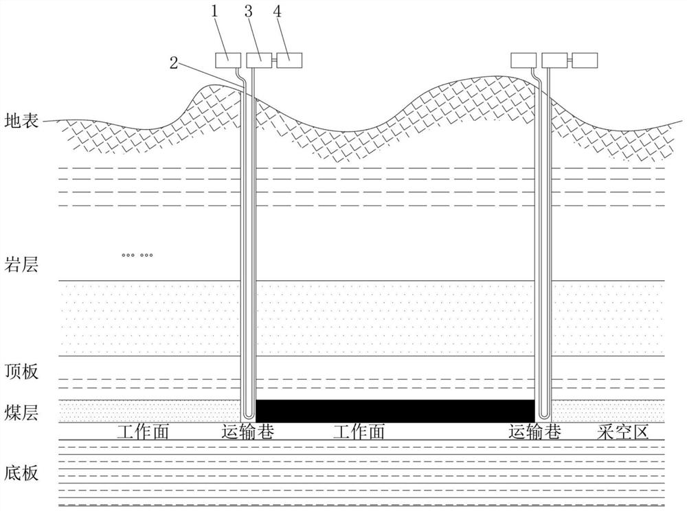
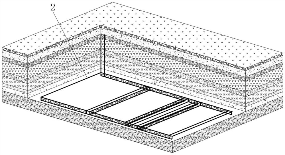
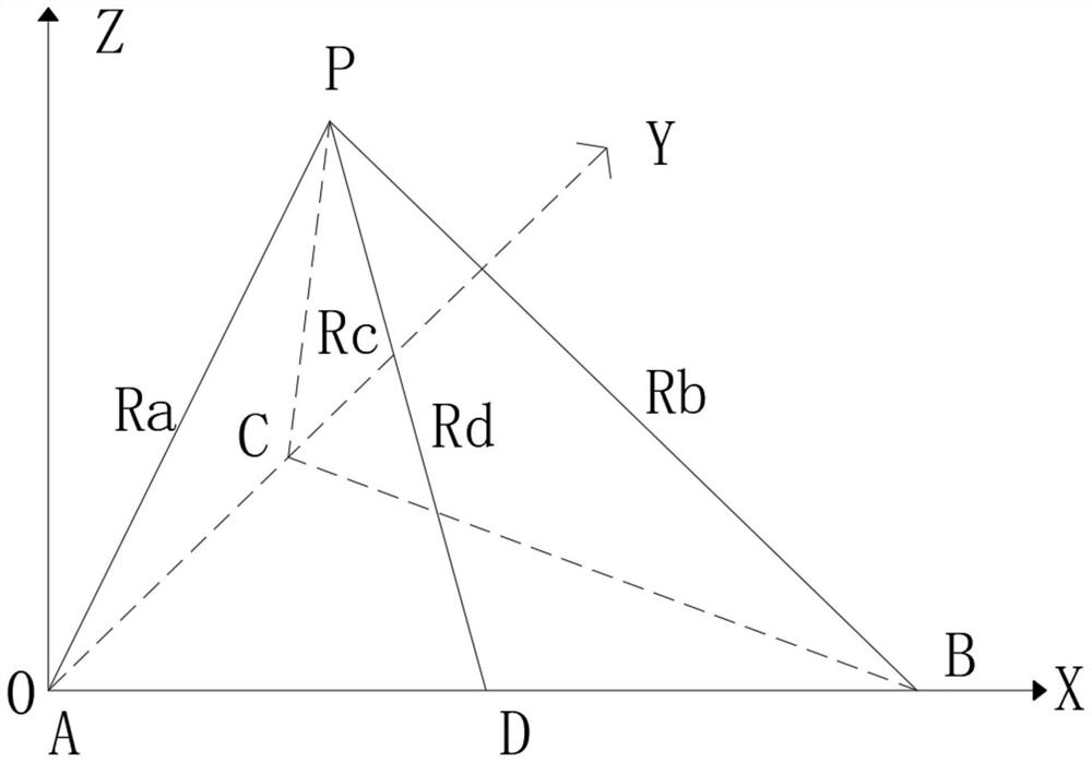
[0038] Such as Figure 1-4 As shown, the mine earthquake source location method based on the underground communication optical cable of the coal mine includes the following steps:

[0039] Step 1: Use the underground communication optical cable 2 as the carrier, connect one end of the communication optical cable 2 to the laser 1 on the ground, connect the other end of the communication optical cable 2 to the wavelength division multiplexer 3, and connect one end of the wavelength division multiplexer 3 Connected with a polarization measuring instrument 4;

[0040] Step 2: By controlling the laser 1 to send an optical signal with a polarization state to the communication optical cable 2, the polarimeter 4 at the other end of the communication opti...


PUM


Abstract

The invention relates to the technical field of mine earthquake source positioning, and discloses a mine earthquake source positioning method based on a coal mine underground communication optical cable, which comprises the following steps of: adopting the mine underground communication optical cable as a carrier, connecting one end of the communication optical cable with a laser on the ground, and connecting the other end of the communication optical cable with a wavelength division multiplexer, wherein one end of the wavelength division multiplexer is connected with a polarization measuring instrument; controlling a laser to emit an optical signal with a polarization state to a communication optical cable, and enabling a polarization measuring instrument at the other end of the communication optical cable to demodulate the received optical signal so as to obtain a peak value delta s1max of a first Stokes parameter s1 of all measuring points on the communication optical cable. According to the invention, the optical fiber polarization information is used for sensing, and the existing mining communication optical cable in the coal mine is innovatively used for replacing a special strain sensing optical cable which is expensive and difficult to lay, so that the problems of single arrangement position, small sensor coverage range, limited monitoring range and the like of the existing micro-seismic monitoring system in the coal mine can be effectively solved.

Description

technical field [0001] The invention relates to the technical field of mine earthquake source positioning, in particular to a mining earthquake source positioning method based on underground communication optical cables in coal mines. Background technique [0002] As the country vigorously promotes the "Internet +" industry solutions and the construction boom of intelligent mines, more and more advanced intelligent equipment and devices are applied to coal mines to meet the ever-growing mine safety monitoring needs and solve coal mine problems. The existing monitoring system has problems such as poor disaster resistance, inconvenient installation, and small monitoring range, so as to improve the safety production and safety monitoring level of coal mines. Especially for the traditional mining earthquake monitoring system, the microseismic sensor probe and the data acquisition host are connected by wires, and generally only 8 to 12 channels of the same type of sensing data ca...

Claims


Application Information

Patent Timeline
IPC IPC(8): G01V1/40G01V1/30G01V1/28G01V1/22G01S17/06G01B11/16
CPCG01V1/40G01V1/226G01V1/28G01V1/30G01S17/06G01B11/168Y02A90/30
Inventor 柴敬欧阳一博张丁丁
Owner XIAN UNIV OF SCI & TECH
Why Eureka
Eureka Blog
Learn More