Eureka AIR delivers breakthrough ideas for toughest innovation challenges, trusted by R&D personnel around the world.

MIMO-OFDM-Based Flexible Rate Intra-Data Center Network

Active Publication Date: 2014-02-27
NEC CORP
View PDF4 Cites 75 Cited by
  • Summary
  • Abstract
  • Description
  • Claims
  • Application Information

AI Technical Summary

Benefits of technology

The present invention is a flexible rate network for data centers that allows for efficient transfer of information between servers and racks. It uses MIMO-OFDM technology to convert data into multiple optical signals and then route them to their destination using a cyclic interleaver and photodetectors. The network can easily adapt to changes in data demand and provides a reliable and efficient infrastructure for data centers. The technical effects include reduced latency, improved bandwidth utilization, and improved reliability.

Problems solved by technology

Many of the Internet applications are hosted in the data center servers (such as cloud computing application, search engine, etc.) and are data-intensive and require large degree of interactions among the servers in the data center.
In the intra-data center network, the traffics among these servers are usually dynamic in nature and often busty.
Therefore the intra-data center networks are facing challenging demand such as high channel bandwidth, flexible bandwidth configuration, low latency, high network throughput.
Also, current data centers rely on electronic router to perform these interconnection functions, this consumes large amount of power and generates large volume of heat, which in turn requires more power for cooling.
However, currently the optical technology in the intra-data center application is only for point-to-point links, which utilizes only the advantage of large bandwidth.
Such network lacks flexibility.
And it does not offer the capability to share the bandwidth as the traffic pattern changes.
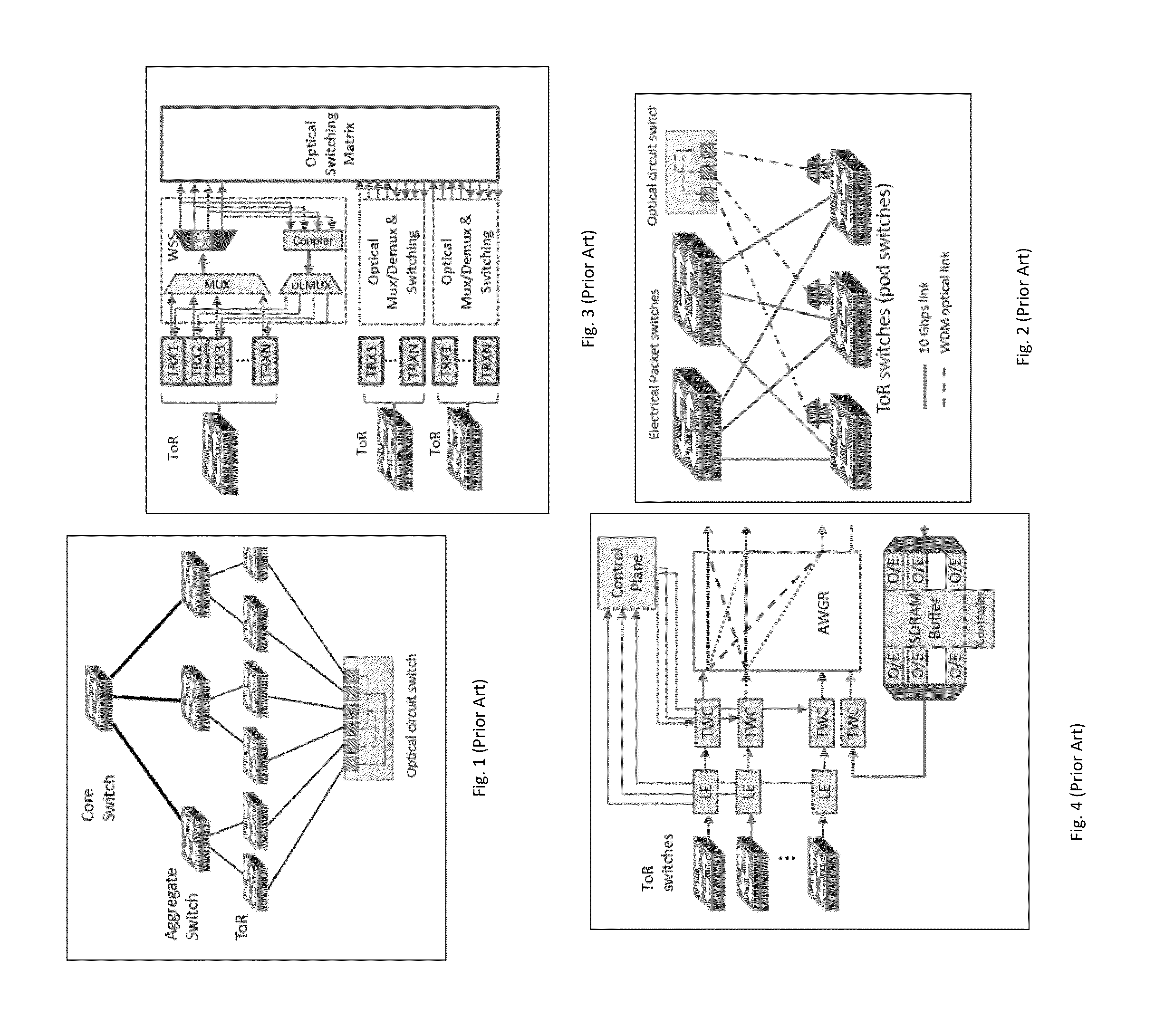
Since the traffics within a rack is relatively smaller and the servers are physically located closer (thus easier to interconnect), the focus of the intra-data center network is on how to efficiently switch among the ToRs, since the ToR, the aggregate switch and the core switch in this architecture have high power consumption and cause latency in the traffic.
This architecture requires a large sale core optical circuit switch, which is costly and present a large single point-of-failure.
It also does not offer bandwidth sharing capability (unless it is done through electrical switch).
Having both electrical switching system and optical switching system makes the network larger and more costly.
This architecture also has the disadvantages of requiring large scale optical circuit switch and not able to share optical bandwidth.
The addition of WSS also increases the hardware cost.
However this remains at lab prototype level and not yet feasible in commercial deployment.
A disadvantage is that it requires electrical buffer for congestion management.
This OEO (optical-electrical-optical) scheme is power hungry and causes latency.
Also, it uses TWC for wavelength tuning, which is quite costly.
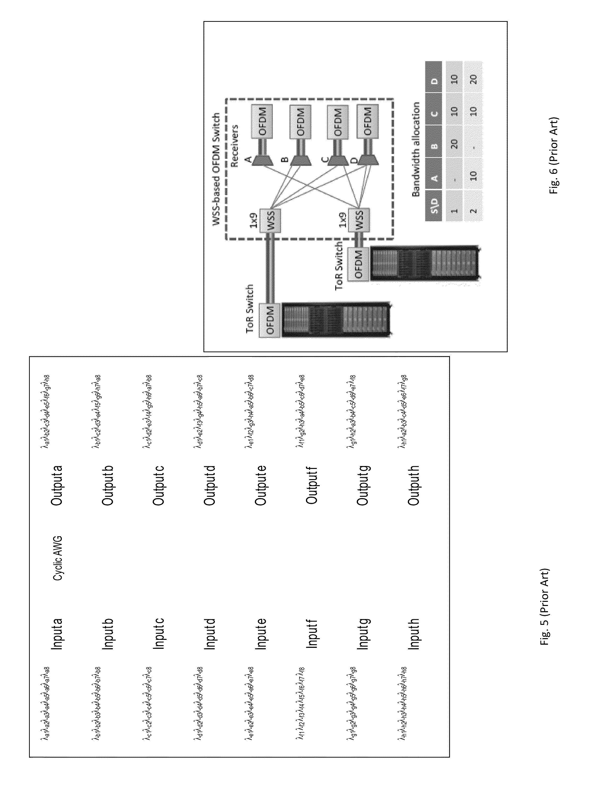
The disadvantages include the requirement of large quantities of TWCs, tunable lasers and CAWGs, which is very costly.
This architecture also requires multiple CAWGs and multiple arrays of wavelength converters, which is very costly.
Besides that, it require arrays of wavelength switches and different optical delay lines for time buffer, which adds the hardware cost even further.
Also, this architecture does not provide sharing of bandwidth between ToRs.
The disadvantages of this architecture include: (1) It requires a flexible grid WSS for each ToR, which is not commonly available, has limited granularity, has limited port count (commercial prototypes are up to 1×9, therefore cannot support the data center network which has typically 100s or 1000s of ToRs), and costly.
(2) It requires guard bands between subcarrier bands for different output ports, which leads to less efficient spectrum utilization.
(4) The granularity is still not fine enough for efficient flexible bandwidth sharing.
(5) It requires either high port count optical coupler (large optical loss) or WSS (costly) at each receiver to multiplex the switched signals.

Method used


Image

  • MIMO-OFDM-Based Flexible Rate Intra-Data Center Network
  • MIMO-OFDM-Based Flexible Rate Intra-Data Center Network
  • MIMO-OFDM-Based Flexible Rate Intra-Data Center Network

Examples


Embodiment Construction

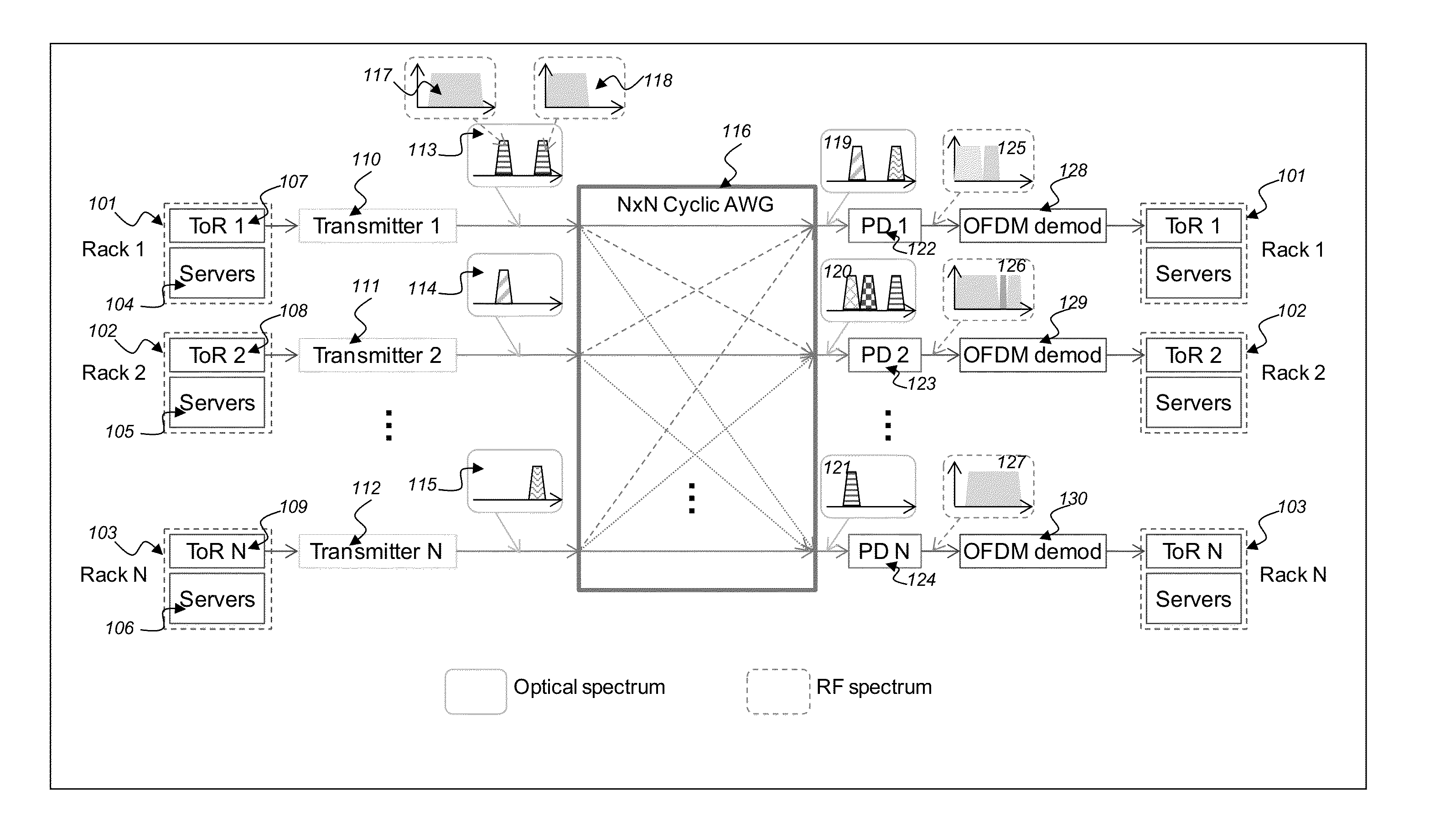
[0040]The present invention uses a “CAWG+electrical OFDM+parallel signal detection” method to perform switching in the data center network. It has the benefit of optical layer switching (high bandwidth, low power consumption and heat dissipation). It combines the benefit of CAWG architecture, but not requiring TWC. By using electrical OFDM (instead of optical OFDM), the granularity for the bandwidth sharing is much finer. It also does not require WSS or optical core switch, and uses only a single receiver to receive multiple incoming signals (through the parallel signal detection technology), therefore reduces optical component cost, improves reliability, and allows fast switching / routing. It does not require electrical buffer.

[0041]Turning now to the block diagram of FIG. 1, showing aspects of load management and CO2 emission reduction for configuring second life battery energy storage

[0042]FIG. 7 shows the schematic of the proposed MIMO OFDM flexible rate intra-data center network...


PUM


Abstract

An optical network includes receiving inter-rack traffics from transmitter racks, converting by transmitters the inter-rack traffics to respective wavelength division multiplexing WDM optical signals, receiving and routing by a cyclic interleaver the optical signals from the transmitters to output ports in a cyclic manner, converting respective routed optical signals from the cyclic interleaver into respective electrical signals, and demodulating OFDM formats from respective converted optical signals containing signals for respective receiver racks.

Description

RELATED APPLICATION INFORMATION[0001]This application claims priority to provisional application No. 61 / 599,611 filed Feb. 16, 2012, the contents thereof are incorporated herein by referenceBACKGROUND OF THE INVENTION[0002]The present invention relates generally to optical networks, and more particularly, to multiple-in-multiple-out orthogonal frequency division multiplexing MIMO-OFDM based flexible rate intra-data center network.[0003]The global Internet traffic is growing rapidly. Many of the Internet applications are hosted in the data center servers (such as cloud computing application, search engine, etc.) and are data-intensive and require large degree of interactions among the servers in the data center. (To distinguish from the communication network between different data centers (i.e. the “inter-data center network”), this network of interconnects among the servers in a data center is called the “intra-data center network” here. In some literatures, this is simply called “d...

Claims


Application Information

Patent Timeline
IPC IPC(8): H04L27/26
CPCH04L27/2649H04L27/2697H04J14/0269H04J14/0298H04Q2011/0032
Inventor JI, PHILIP NANWANG, TINGAONO, YOSHIAKI
Owner NEC CORP
Why Eureka
Eureka Blog
Learn More