
Left-right hand circular polarization reconfigurable implantable antenna and reconfigurable method

An implantable, circularly polarized technology, applied in the field of biomedical telemetry, can solve the problems of circular polarization mismatch, user's body influence, large occupied volume, etc., and achieve the effect of large impedance bandwidth and reliable transmission distance

Pending Publication Date: 2022-01-28
SOUTH CHINA UNIV OF TECH
View PDF0 Cites 0 Cited by
  • Summary
  • Abstract
  • Description
  • Claims
  • Application Information

AI Technical Summary

Problems solved by technology

At this stage, there are still many problems with circularly polarized implantable antennas. One is that today’s circularly polarized implantable antennas only consider a single circular polarization method, which reduces the scope of application of the antenna, and may also cause circular polarization. The mismatch between polarization; the second is that the circularly polarized implantable antenna takes up too much space, which will affect the user's body
[0003] Most of the current implantable antenna designs have the disadvantages of excessive volume, polarization mismatch, and narrow bandwidth, which make implantable devices unable to adapt to the complex environment in practical applications.

Method used


Image

  • Left-right hand circular polarization reconfigurable implantable antenna and reconfigurable method
  • Left-right hand circular polarization reconfigurable implantable antenna and reconfigurable method
  • Left-right hand circular polarization reconfigurable implantable antenna and reconfigurable method

Examples


Embodiment 1

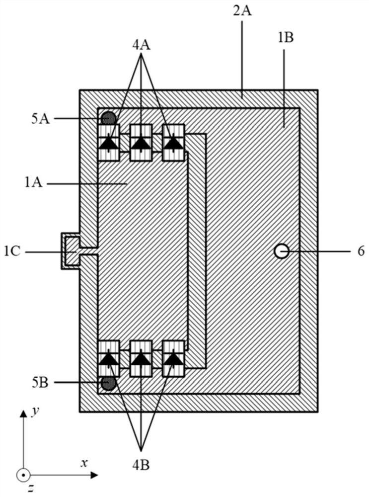
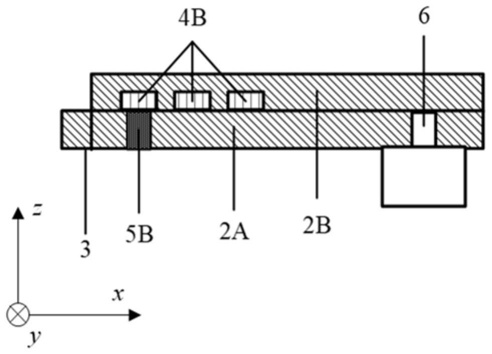
[0036] Such as Figure 1-Figure 2 As shown, a reconfigurable implantable antenna with left and right circular polarization for mobile medical care includes an upper dielectric substrate 2B and a lower dielectric substrate 2A, both dielectric substrates use 0.635mm Rogers 3010 substrates, and the lower dielectric substrate An antenna radiation unit is arranged on the upper surface of the dielectric substrate, and a metal floor is arranged on the lower surface thereof. The antenna radiating unit is divided into two parts by a U-shaped groove. The lower dielectric substrate and the antenna radiating unit are both rectangular in structure. The U-shaped groove is composed of three successively vertical groove lines, and the two end groove lines are connected with the antenna radiation unit. One side of the U-shaped groove is connected, and the part surrounding the U-shaped groove is called the central metal 1A, and the other part is called the peripheral metal 1B.

[0037] The upp...

Embodiment 2

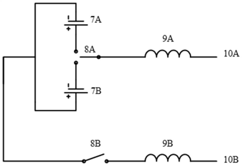
[0062] An implanted device includes the implanted antenna. The implanted antenna includes an antenna radiation unit, an upper dielectric substrate, a lower dielectric substrate, a metal floor, a diode group, a metal via, a coaxial feed structure, and a DC feed structure. The antenna radiation unit is located at a high dielectric constant The upper surface of the lower dielectric substrate, the metal floor is located on the lower surface of the high dielectric constant lower dielectric substrate. Radio frequency switching diodes are distributed on the antenna radiation unit. The DC feed system is connected to the antenna through a radio frequency isolation inductor, and the control circuit switch can switch the circular polarization state of the antenna.


PUM

PropertyMeasurementUnit
lengthaaaaaaaaaa
lengthaaaaaaaaaa
lengthaaaaaaaaaa

Abstract

The invention discloses a left-right hand circular polarization reconfigurable implantable antenna and a reconfigurable method. The antenna comprises a lower-layer dielectric substrate and an upper-layer dielectric substrate, an antenna radiation unit is arranged on the upper surface of the lower-layer dielectric substrate, a metal floor is arranged on the lower surface of the lower-layer dielectric substrate, the upper dielectric substrate covers the antenna radiation unit, the antenna radiation unit is divided into two parts by a U-shaped groove, and two arms of the U-shaped groove are provided with switching diode groups used for connecting the two parts of the antenna radiation unit. The antenna has the advantages of large impedance bandwidth, miniaturization, circular polarization, polarization mismatch resistance, high gain, switchable left-hand circular polarization and right-hand circular polarization and the like, and can be applied to mobile medical communication to solve the problem of polarization mismatch.

Description

technical field [0001] The invention relates to the field of biomedical telemetry, in particular to a reconfigurable implantable antenna with left and right circular polarization and a reconfigurable method. Background technique [0002] Compared with traditional medical methods, mobile medical treatment can reduce the pain of patients, reduce costs, and remote diagnosis. Due to the characteristics of human body movement and posture changes, the advantage of applying circular polarization in implantable devices is that it can resist biomedical The polarization mismatch caused by the signal receiving angle. At this stage, there are still many problems with circularly polarized implantable antennas. One is that today’s circularly polarized implantable antennas only consider a single circular polarization method, which reduces the scope of application of the antenna, and may also cause circular polarization. The second is that the circularly polarized implantable antenna takes...

Claims


Application Information

Patent Timeline
Patent Type & Authority Applications(China)
IPC IPC(8): H01Q15/24H01Q1/50
CPCH01Q15/24H01Q1/50
Inventor 刘雄英洪杰
Owner SOUTH CHINA UNIV OF TECH
Learn More