
Precipitated sludge concentration device and concentration method for epoxy resin wastewater treatment

A technology for wastewater treatment and sludge concentration, which is applied to the feeding/discharging device, separation method, precipitation separation, etc. of the sedimentation tank. The effect of large processing capacity, reduced cost investment and small space occupation

Pending Publication Date: 2022-02-01
黄山五环科技有限公司
View PDF1 Cites 0 Cited by
  • Summary
  • Abstract
  • Description
  • Claims
  • Application Information

AI Technical Summary

Problems solved by technology

[0004] Due to the large amount of wastewater treatment, in order to treat wastewater efficiently, the water tanks, PH adjustment pools, pools, etc. used in this scheme occupy a large installation area, and the production cost is relatively high.

Method used


Image

  • Precipitated sludge concentration device and concentration method for epoxy resin wastewater treatment
  • Precipitated sludge concentration device and concentration method for epoxy resin wastewater treatment
  • Precipitated sludge concentration device and concentration method for epoxy resin wastewater treatment

Examples


Embodiment 1

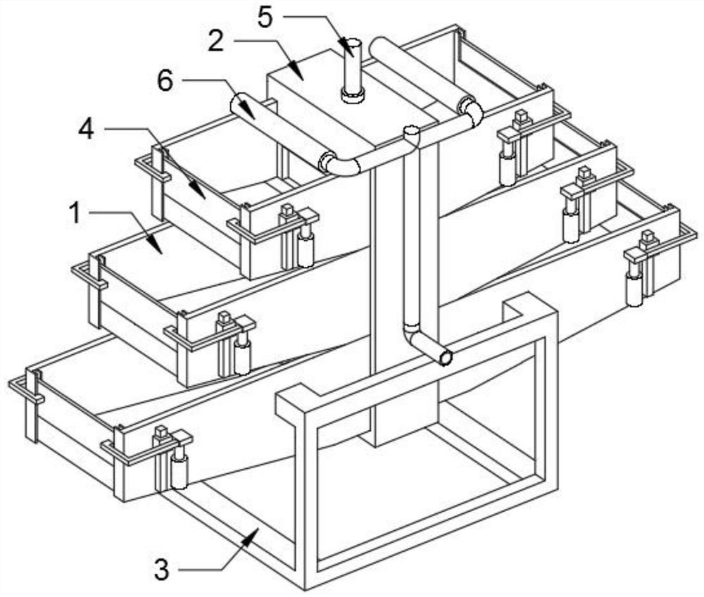
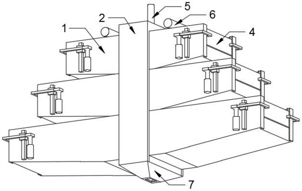
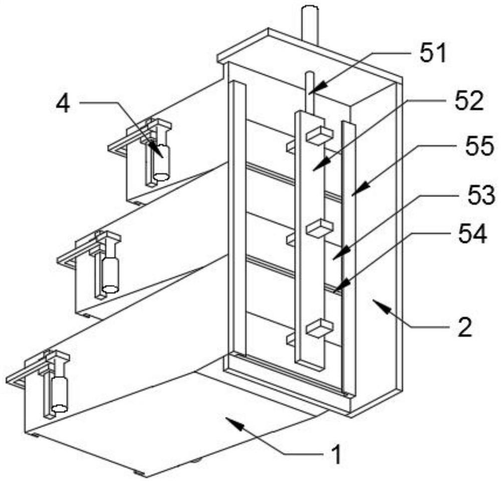
[0029] Such as figure 1 , figure 2 , image 3 and Figure 5 As shown, a sedimentation sludge thickening device for epoxy resin wastewater treatment is assembled from the following components:

[0030]

[0031]

[0032] Assembly instructions: Arrange and fix the pool body 1 on both sides with the base shell 2 as the center. Corresponding to the surface of the base shell 2, a sewage outlet 54 is opened, and the two sides of the sewage outlet 54 are symmetrically welded with guide rails 55. A sealing plate 53 is slidably arranged between the guide rails 55, and is aligned with the sewage outlet 54. The sealing plate 53 is fixedly connected with the connecting plate 52.

[0033] Working principle: When injecting waste water, connect the liquid pipe 61 with the waste water driving equipment, the waste water is introduced into the nozzle 62, and dispersed into the pool body 1 through the nozzle hole 63, and the waste water fills each pool body 1 sequentially from top to bo...

Embodiment 2

[0035] Such as figure 1 and Figure 4 As shown, a sedimentation sludge thickening device for epoxy resin wastewater treatment is assembled from the following components:

[0036]

[0037]

[0038] Assembly instructions: Arrange and fix the pool body 1 on both sides with the base shell 2 as the center. The electric push rod 43 is installed on both sides of the body 1, and the connecting frame 44 is fixed on the top, and the connecting frame 44 is connected with the water level plate 45. fixed.

[0039] Working principle: the water level plate 45 blocks the sinking tank 47, and the top of the water level plate 45 is the highest position of the liquid level. Open the electric push rod 43 to drive the connecting frame 44 to adjust the water level plate 45 to adjust the height of the liquid level in the pool body 1. The clear layer on top of the pellet was drained.

[0040] A kind of sedimentation sludge thickening method of epoxy resin wastewater treatment, concrete step...


PUM


Abstract

The invention relates to the field of epoxy resin wastewater treatment, in particular to a precipitated sludge concentration device and concentration method for epoxy resin wastewater treatment. The precipitated sludge concentration device for epoxy resin wastewater treatment comprises a base shell, a plurality of pool bodies are symmetrically arranged on the two sides of the base shell in a stacked mode, the ends, close to the base shell, of the pool bodies are flush, and the other end of each of the pool bodies is sequentially lengthened outwards from top to bottom. The two stacked position adjusting mechanisms are adopted, wastewater is guided from top to bottom to be concentrated and precipitated, the single-time treatment capacity is large, the occupied space is small, the cost input is reduced, meanwhile, the base shell arranged in the middle is matched with the pollution discharge mechanism, concentrated precipitates can be synchronously discharged, and the treatment difficulty is simplified.

Description

technical field [0001] The invention relates to the field of epoxy resin wastewater treatment, in particular to a sedimentation sludge concentration device and concentration method for epoxy resin wastewater treatment. Background technique [0002] The excellent physical, mechanical and electrical insulation properties of epoxy resin, the bonding performance with various materials, and the flexibility of its use process are not available in other thermosetting plastics. Therefore, it can be made into coatings, composite materials, casting materials, adhesives, molding materials and injection molding materials, and is widely used in various fields of the national economy. Wastewater, in order to meet environmental protection production requirements, advanced treatment of wastewater is required. [0003] The patent document CN112624422A proposes a recycling device for epoxy resin production wastewater. The water quality obtained through filtration is better. Two aeration plat...

Claims


Application Information

Patent Timeline
Patent Type & Authority Applications(China)
IPC IPC(8): B01D21/02B01D21/24
CPCB01D21/00B01D21/2405B01D21/2444B01D21/245
Inventor 汪年华罗乐平程殿辉王永垒江蓉
Owner 黄山五环科技有限公司
Learn More