Multifunctional combined sludge discharge device

A sludge discharge device and combined technology, applied in sludge treatment, fixed filter element filter, water/sludge/sewage treatment, etc., can solve the problems of shortened process flow, high investment cost, difficult operation, etc. The effect of simple operation, simple equipment structure and less electrical equipment

Active Publication Date: 2022-02-01
JIANGSU JINGYUAN ENVIRONMENTAL PROTECTION
View PDF7 Cites 0 Cited by
  • Summary
  • Abstract
  • Description
  • Claims
  • Application Information

AI Technical Summary

Problems solved by technology

[0006] The purpose of the present invention is to provide a multifunctional combined sludge discharge device, which solves the problems of the traditional sludge discharge device such as easy fouling, difficult operation, single function, and high investment cost, and at the same time shortens the process of sludge transportation to sludge concentration and dehydration process, achieving the goal of efficient sludge dewatering with integrated functions of sludge concentration and dehydration

Method used


Image

  • Multifunctional combined sludge discharge device

Examples


Embodiment 1

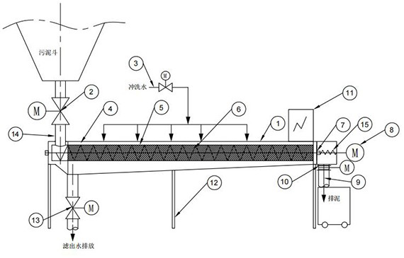
[0030] A multi-functional combination slurry device, such as figure 1 As shown, including the apparatus body 1, the apparatus body portion is an outer inner circular type, and the internal pipe structure; the lower portion of the apparatus main body is placed on the leg 12, and the support load load of the leg 12 is supported; the apparatus body 1 end Connecting in the mud gate 14, the lower portion of the other end is connected to the slot 9.

[0031] like figure 1 As shown, the upper end of the inverting 14 is connected to the sludge strip, and the sludge produced by the ground sludge concentrator / sludge precipitation tank is stored in the lower part of the pool body, typically set timing according to the sludge residence time design of the pool. During the mud, according to the sludge characteristics according to the sludge characteristics, the excreted amount of mud has reached 3% to 5%;

[0032] There is a sludge in the lower end of the mud 9, and the sludge (water content ...

Embodiment 2

[0048] This embodiment is substantially the same as the embodiment of the embodiment, and the difference is:

[0049] The opening and closing device also includes a fender 7, and the fender 7 is actively connected to the apparatus body 1, and its motion position includes a closed bit to stand at one end of the cylindrical filter 5 and an open position away from the cylindrical filter 5;

[0050] In this embodiment, the fender 7 is slipped in the main shaft direction, and the device body 1 is provided with a telescopic spring 15 between the end surface and the fender 7, and the retractable spring 15 is set to the main shaft and fixed. The fender 7 welding is fixed, and the retractable spring 15 drives the fender 7 against one end of the cylindrical filter 5;

[0051] The spiral pusher continuously pushes the sludge after dehydration to the left side of the fender 7, and when the pressure is greater than the thrust of the telescopic spring 15, the slime 7 is opened, the sludge after...


PUM


Abstract

The invention discloses a multifunctional combined sludge discharge device, relates to the technical field of sewage treatment, and solves the problems that a traditional sludge discharge device is easy to block, difficult to operate, single in function, high in investment cost and the like, the multifunctional combined sludge discharge device comprises a device body, one end of the device body is provided with a sludge inlet, and the other end of the device body is provided with a sludge outlet, a main shaft is rotatably connected in the device body, a spiral blade for pushing materials from the sludge inlet to the sludge outlet when the main shaft rotates is arranged on the main shaft, a cylindrical filter screen sleeved outside the main shaft is also connected in the device body, the sludge inlet is communicated with the inner side of the cylindrical filter screen, and the outer side of the cylindrical filter screen is communicated with a drainage valve; and an opening and closing device positioned between the inner side of the cylindrical filter screen and the sludge outlet is arranged in the device body. The technological process from sludge conveying to sludge thickening and dewatering is shortened, and the efficient sludge discharging and dewatering effect integrating multiple functions of sludge thickening and dewatering is achieved.

Description

Technical field [0001] The present invention relates to the field of sewage treatment, and in particular, to a multifunctional combined slurry device. Background technique [0002] The mortar unit is an indispensable part in the sewage treatment system. The traditional sem mitral device is multi-sem mud pipe to deliver sludge to the sludge concentration tank / sludge sedimentation tank, or pressurized to the sludge via the mud pump. After the dehydration device is dehydrated, it will be safely disposed. This process is defects as follows: [0003] 1) There are many indigenous equipment, including mud tunnel, valve, sludge pump, sludge dehydration equipment, electronically controlled equipment, and the above-mentioned multi-device combination operation leads to many operating steps, and the equipment maintenance is high; [0004] 2) The process segment is generally intermittent operation. It is too long and laid in the mud tube. The sludge causing a large amount of sludge accumula...

Claims


Application Information

Patent Timeline
Patent Type & Authority Applications(China)
IPC IPC(8): C02F11/121B01D29/35B01D29/58B01D29/68B01D29/64B01D35/143
CPCC02F11/121B01D29/35B01D29/58B01D29/68B01D29/6415B01D35/143
Inventor 李武林刘琴琴王辰秦小波李桂银
Owner JIANGSU JINGYUAN ENVIRONMENTAL PROTECTION
Why Eureka
Try Eureka