Self-shearing cover plate assembly for rapid winding arrangement
A cover plate and wire winding technology, which is applied in the direction of electric components, vehicle components, electrical components, etc., can solve the problems of inadvertently binding lead wires of different phases, consuming the energy of the operator, and low work efficiency, so as to shorten the finishing time , Accelerate the efficiency of sorting, and facilitate the collection
- Summary
- Abstract
- Description
- Claims
- Application Information
AI Technical Summary
Problems solved by technology
Method used
Image
Examples
specific Embodiment 1
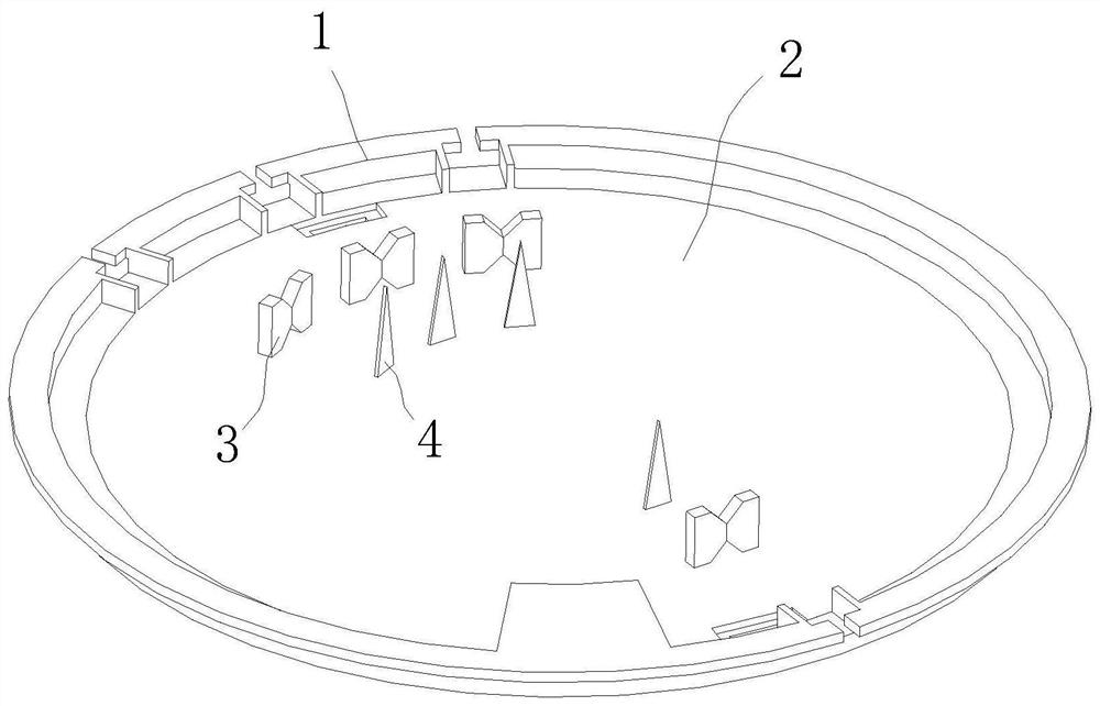
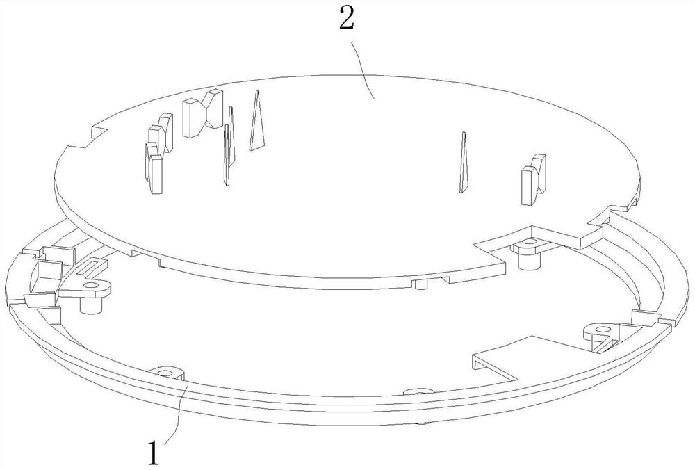
[0051] Specific embodiment one: please refer to Figure 1-6 A self-shearing deck assembly for rapid wire-winding finishing, including
[0052] The cover plate 1 is ring-shaped, connected to the upper end of the hub motor bracket, and has a collection port. The collection port includes A port, B port, C port and common port to collect A-phase lead wires, B-phase lead wires, and C-phase lead wires. Lead wire and common lead wire; A-phase lead wire, B-phase lead wire, C-phase lead wire and common lead wire are lead wire 5;
[0053] The cover plate 2 is detachably connected to the inner side of the cover plate 1, including a wire harness part 3 and a wire tangent part 4;
[0054] Each collection port is provided with a corresponding beamline part 3;
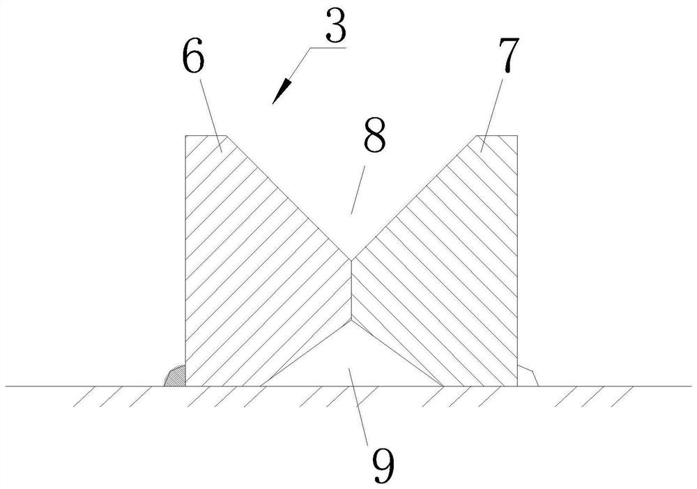
[0055] The wire harness part 3 includes a fixed part 6 and a rotating part 7, and the fixed part 6 and the rotating part 7 are in magnetic contact;
[0056]The side of the fixing part 6 close to the rotating part 7 is divided into...
specific Embodiment 2
[0065] Specific embodiment two: please refer to Figure 7-8 A self-shearing cover plate assembly for fast winding and finishing is different from the first embodiment in that both the fixed part 6 and the rotating part 7 have circular arc surfaces; the outer edge contact surfaces of the two circular arc surfaces are resisting joint, the fixed part 6 and the rotating part 7 are in line contact;
[0066] Both the abutting surface 602 and the two abutting surfaces 702 are circular arc surfaces.
[0067] The introduction channel 8 includes an arcuate portion on the upper side of the abutment of the fixing member 6 , an arcuate portion on the upper side of the abutment of the rotating member 7 , an introduction surface 601 and two introduction surfaces 701 .
[0068] Such arrangement makes it easy for the lead wire 5 to slide into the wire harness channel 9. At the same time, because the abutting surface 602 and the abutting two surfaces 702 are all circular arc surfaces, although...
specific Embodiment 3
[0069] Specific embodiment three: please refer to Figure 9-12 A self-shearing cover plate assembly for fast winding and finishing is different from the specific embodiment 1 in that in a free state, the two walls forming the introduction channel 8 form an acute angle; wherein the wall belonging to the fixing part 6 is inclined relative to the horizontal plane , the wall belonging to the rotating part 7 is a horizontal plane, and the wall belonging to the rotating part 7 is located above the wall belonging to the fixing part 6 .
[0070] In the free state, the fixed part 6 and the rotating part 7 are in contact with each other, and the abutment is composed of two planes, wherein the plane belonging to the fixed part 6 and the plane of the rotating part 7 are inclined surfaces, and the plane belonging to the fixed part 6 It is perpendicular to the wall surface of the fixing part 6 forming the introduction channel 8 , that is, the plane belonging to the fixing part 6 is inclined...
PUM
 Abstract
Description
Claims
Application Information
 - R&D
- Intellectual Property
- Life Sciences
- Materials
- Tech Scout
- Unparalleled Data Quality
- Higher Quality Content
- 60% Fewer Hallucinations
Browse by: Latest US Patents, China's latest patents, Technical Efficacy Thesaurus, Application Domain, Technology Topic, Popular Technical Reports.
© 2025 PatSnap. All rights reserved.Legal|Privacy policy|Modern Slavery Act Transparency Statement|Sitemap|About US| Contact US: help@patsnap.com


