Optical frequency transmission device and method based on time delay

A frequency transfer and optical technology, applied in the field of delay-based optical frequency transfer devices, can solve the problems of frequency transfer system compensation for bandwidth-limited fiber link delay, unsuitable for optical frequency transfer, etc., to improve stability, suppress The effect of phase noise

Active Publication Date: 2022-02-01
SHANGHAI JIAO TONG UNIV
View PDF14 Cites 3 Cited by
  • Summary
  • Abstract
  • Description
  • Claims
  • Application Information

AI Technical Summary

Problems solved by technology

In addition, as the fiber distance increases, the compensation bandwidth of the frequency transfer system will be limited by the delay of the fiber link
In 2014, the Italian Astronomical Observatory proposed a method of electrical delay to reduce the delay introduced by optical fiber links [see Calosso, C.E., Bertacco, E.K., Calonico, D., Clivati, C., Costanzo, G.A., Frittelli, M .,Levi,F.,Micalizio,S.,Mura,A.and Godone,A.,2015.Doppler-stabilized fiber link with 6dB noise improvement below the classical limit.Optics letters,40(2),pp.131-134 .], but this method needs to predict the data and is not suitable for the requirements of optical frequency transmission

Method used


Image

  • Optical frequency transmission device and method based on time delay
  • Optical frequency transmission device and method based on time delay
  • Optical frequency transmission device and method based on time delay

Examples


Embodiment Construction

[0046] Below in conjunction with embodiment and accompanying drawing, the present invention will be further described, and present embodiment is carried out on the premise of technical solution of the present invention, has provided detailed implementation mode and and specific work flow, but protection scope of the present invention is not limited to the following the described embodiment.

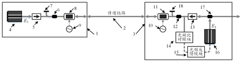
[0047] see first figure 1 , figure 1 It is a structural schematic diagram of Embodiment 1 of the delay-based optical frequency transmission device of the present invention. It can be seen from the figure that the delay-based optical frequency transmission device of the present invention consists of a local terminal 1, a transmission link 2 and a relay terminal connected in sequence 3 constitute,

[0048] The local terminal 1 is composed of a main laser 4, a first optical isolator 5, a first optical coupler 6, a first Faraday rotating mirror 7, a first acousto-optic frequency shifter 8 a...


PUM


Abstract

The invention discloses an optical frequency transmission device and method based on time delay. The device is composed of a local end, a transmission link and a relay end, wherein the input light signal of the local end is transmitted to the relay end through the transmission link, and the output light signal of the slave laser device of the relay end is transmitted to the local end through the same transmission link and then is reflected back to the relay end again. In the method, two paths of signal light passing through a transmission link arrive at a relay end and then are input into an optical frequency delay comparison unit to obtain a relative frequency deviation between a master laser device and a slave laser device, and the signal frequency of output light of the slave laser device is fed back and controlled by using the relative frequency deviation, so that the frequency between the light signals input from the laser device and the local end is relatively stable. According to the invention, different additional time delays are applied to the two paths of light signals to carry out frequency comparison with a traditional transmission method, so that phase noise introduced by a transmission link can be reduced; and the relay station can perform optical frequency transmission to the next link by adopting a phase compensation mode, so that cascaded optical frequency transmission is realized.

Description

technical field [0001] The invention relates to optical frequency transmission, in particular to a delay-based optical frequency transmission device and an optical frequency transmission method. Background technique [0002] High-precision time-frequency transfer technology plays an important role in basic science, applied science, people's livelihood and national defense. Today, with the continuous improvement of the accuracy and stability of optical atomic clocks, the stable transmission technology of optical frequency signals has also become an important part of building a large-scale optical atomic clock network. However, during the transmission of optical frequency signals, the transmission link will have two effects: (1) The attenuation of the transmission link will cause the power of optical frequency signals to become weak during long-distance transmission. If an optical amplifier is used for power amplification , will introduce additional spontaneous emission noise...

Claims


Application Information

Patent Timeline
Patent Type & Authority Applications(China)
IPC IPC(8): H04B10/69
CPCH04B10/697
Inventor 胡亮王龙吴龟灵刘娇陈建平
Owner SHANGHAI JIAO TONG UNIV
Why Eureka
Try Eureka