Protective device of cutting machine

A protection device and cutting machine technology, applied in welding equipment, laser welding equipment, metal processing equipment, etc., can solve the problems of difficult cleaning, accumulation of dust on the screen, blocking of ventilation passages, etc., to improve heat dissipation efficiency, improve ventilation efficiency, The effect of avoiding tedious work

Inactive Publication Date: 2022-02-08
ANHUI POLYTECHNIC UNIV MECHANICAL & ELECTRICAL COLLEGE
View PDF0 Cites 0 Cited by
  • Summary
  • Abstract
  • Description
  • Claims
  • Application Information

AI Technical Summary

Problems solved by technology

[0003] During the processing of the laser cutting machine, the contact part with the workpiece will generate a high temperature, and the contact part needs to be cooled in time afterwards, but when the device used for heat dissipation is in use, the vents in it may sometimes be in the ventilation process. There will be foreign objects entering the vents, resulting in a decrease in ventilation efficiency or blockage of the ventilation passages. The current vents are often solved by installing a screen, but the screen is easy to accumulate dust, and it is difficult to clean after the screen is blocked. And the screen will also have a certain impact on the ventilation efficiency. Therefore, we propose a protective device for cutting machines

Method used


Image

  • Protective device of cutting machine
  • Protective device of cutting machine
  • Protective device of cutting machine

Examples


Embodiment 1

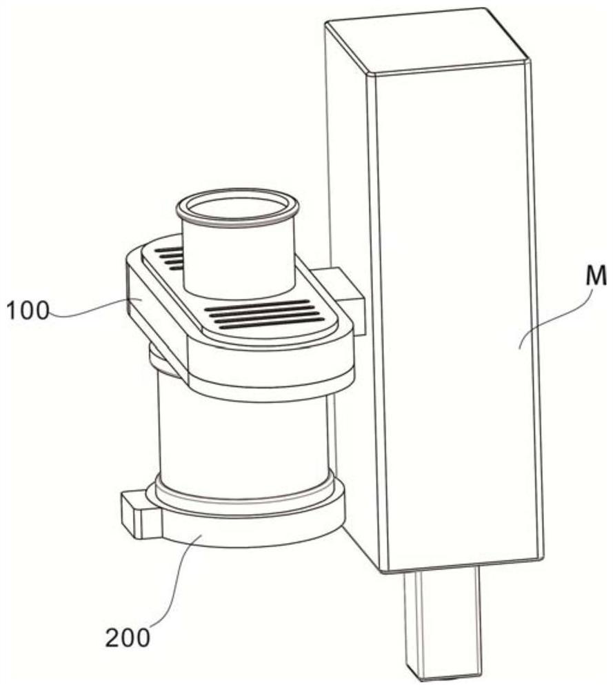
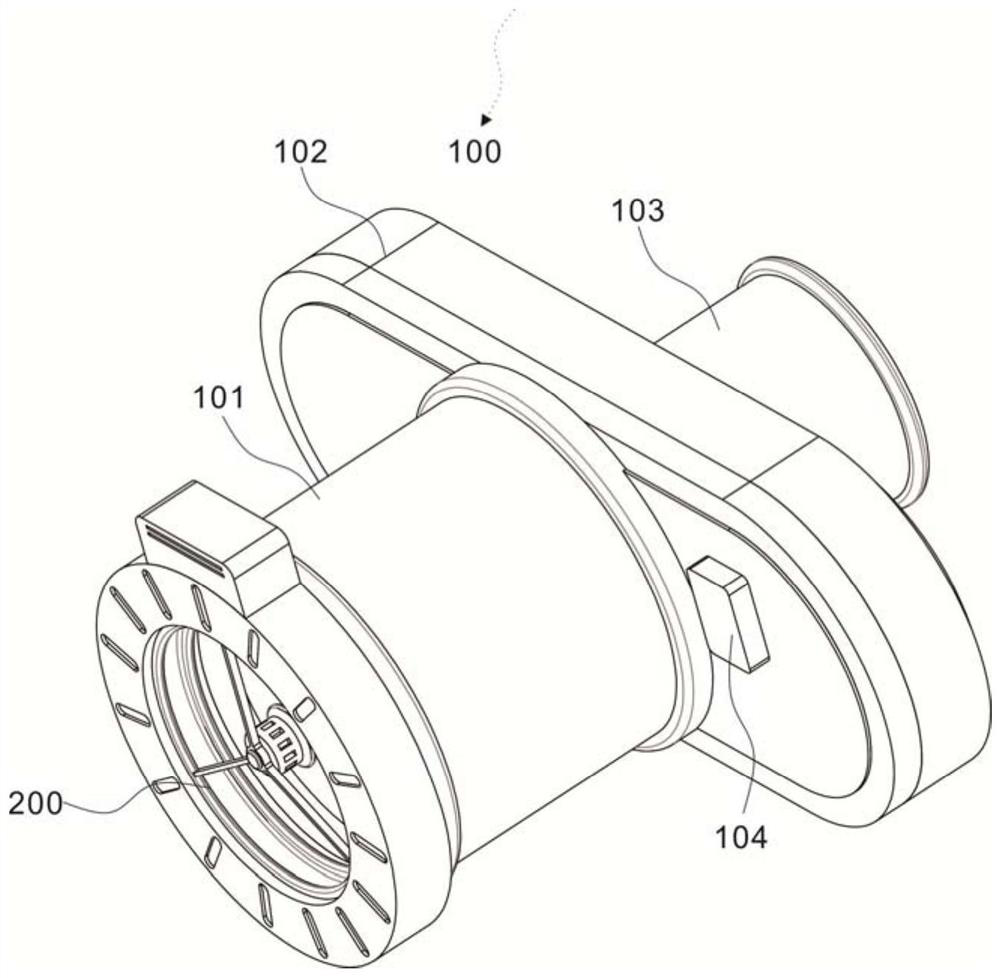
[0027] Example 1: Please refer to figure 1 , the present invention provides a protective device for a cutting machine, comprising: a cutting machine body M; a housing assembly 100, the housing assembly 100 is arranged on one side of the cutting machine body M, and includes an air guide pipe 101, and the end of the air guide pipe 101 is fixedly connected with The waist shell 102, the connecting pipe 103 is fixedly connected to the waist shell 102 surface, and the waist shell 102 surface is provided with a controller; An air guide ring 202 is embedded on the inner surface, and the air guide ring 202 is connected to the air injection device 203 through a connecting pipe;

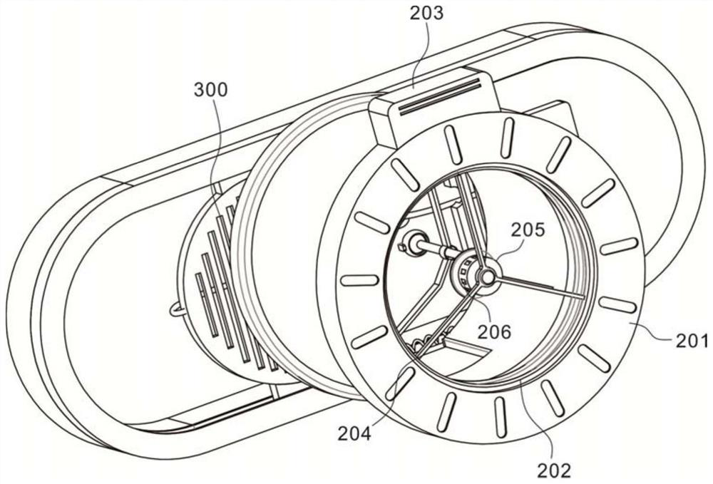
[0028] see figure 2 and image 3 , the center of the wind guide ring 202 is provided with a hollow seat 205, the hollow seat 205 is fixedly set by the triangular bracket 204, the end of the triangular bracket 204 is fixedly connected with the inner wall of the annular seat 201, and the surface of the hollow ...

Embodiment 2

[0031] Example 2: Please refer to Figure 3-5 , the blocking assembly 300 includes a fixed support rod 301 fixed up and down symmetrically in the inner cavity of the waist shell 102, a positioning plate 302 is arranged between the fixed support rods 301, and a guide column 303 is provided on the positioning plate 302, and the guide column 303 One end is fixedly connected to the end of the fixed pole 301, and the other end of the guide column 303 is fixedly connected to the installation bracket 304, and the guide column 303 is provided with a reset spring 305, and the installation bracket 304 is fixed to the inner cavity of the communication pipe 103.

[0032] The guide column 303 moves along the guide column 303 through the control of the push cylinder 306, and the push cylinder 306 is electrically connected to the controller. The air pressure in 209 changes, which drives the positioning plate 302 to move forward along the guide column 303, and releases the tension force on th...


PUM


Abstract

The invention discloses a protective device of a cutting machine, and belongs to the technical field of cutting machines. The device comprises a cutting machine body; a shell assembly, the end part of an air guide pipe being fixedly connected with a waist-shaped shell, and the surface of the waist-shaped shell being fixedly connected with a communicating pipe; a pneumatic balance assembly, an air guide ring being embedded in the inner surface of the annular seat, and the air guide ring being connected with air injection equipment through a connecting pipe; and a blocking assembly, arranged in an inner cavity of the kidney-shaped shell. Air flow is evenly blown to the hollow seat through the air guide ring, when foreign matter enters the air guide pipe, pneumatic balance is broken after the foreign matter passes through the blown air flow surface, air pressure in the spherical sleeve is changed, the positioning disc is driven to move forwards along the guide column, the tensioning acting force on the traction rope is relieved, the blocking plates draw close to each other and are combined under the action of the connecting springs, and the blocking plates are driven to enter the inner cavity of the air guide pipe under the action of the reset springs, so that the ventilation efficiency is improved, the tedious operation of subsequent maintenance is avoided, and the problem of foreign matter blockage is avoided.

Description

technical field [0001] The invention relates to the technical field of cutting machines, in particular to a protective device for cutting machines. Background technique [0002] The laser cutting machine focuses the laser light emitted from the laser device into a high power density laser beam through the optical path system. The laser beam irradiates the surface of the workpiece to make the workpiece reach the melting point or boiling point. At the same time, the high-pressure gas coaxial with the beam will blow away the molten or gasified metal. purpose of cutting. [0003] During the processing of the laser cutting machine, the contact part with the workpiece will generate a high temperature, and the contact part needs to be cooled in time in the follow-up, but when the device for heat dissipation is in use, the vents in it may sometimes be in the ventilation process. There will be foreign objects entering the vents, resulting in a decrease in ventilation efficiency or ...

Claims


Application Information

Patent Timeline
Patent Type & Authority Applications(China)
IPC IPC(8): B23K26/70B23K26/38
CPCB23K26/703B23K26/70B23K26/38
Inventor 王林
Owner ANHUI POLYTECHNIC UNIV MECHANICAL & ELECTRICAL COLLEGE
Why Eureka
Try Eureka