Concrete pavement crushing treatment integrated system

A concrete pavement and crushing machine technology, applied in grain processing, roads, roads, etc., can solve the problems that crushed stones cannot be used directly, crushed stones cannot be collected, and crushed stones cannot be collected by classification, so as to prolong the residence time and improve the screening Effect, effect to improve functionality

Active Publication Date: 2022-02-11
SHANGHAI NO 4 CONSTR
View PDF8 Cites 0 Cited by
  • Summary
  • Abstract
  • Description
  • Claims
  • Application Information

AI Technical Summary

Problems solved by technology

[0004] In view of this, in order to solve the problem that the traditional multi-hammer hydraulic concrete pavement crushing device cannot collect crushed stones after crushing the concrete pavement, Moreover, it is impossible to directly classify and collect g

Method used


Image

  • Concrete pavement crushing treatment integrated system
  • Concrete pavement crushing treatment integrated system
  • Concrete pavement crushing treatment integrated system

Examples


Embodiment 1

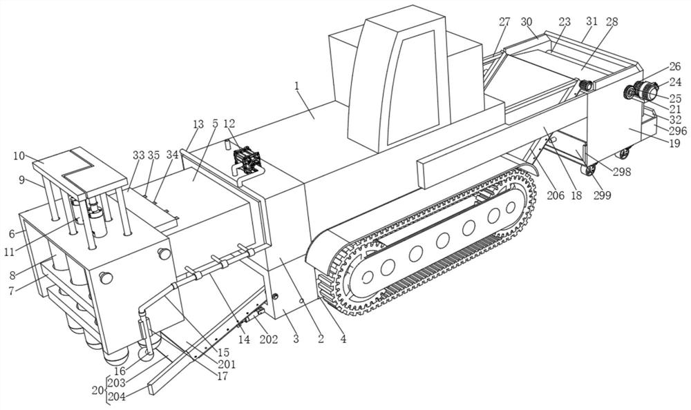
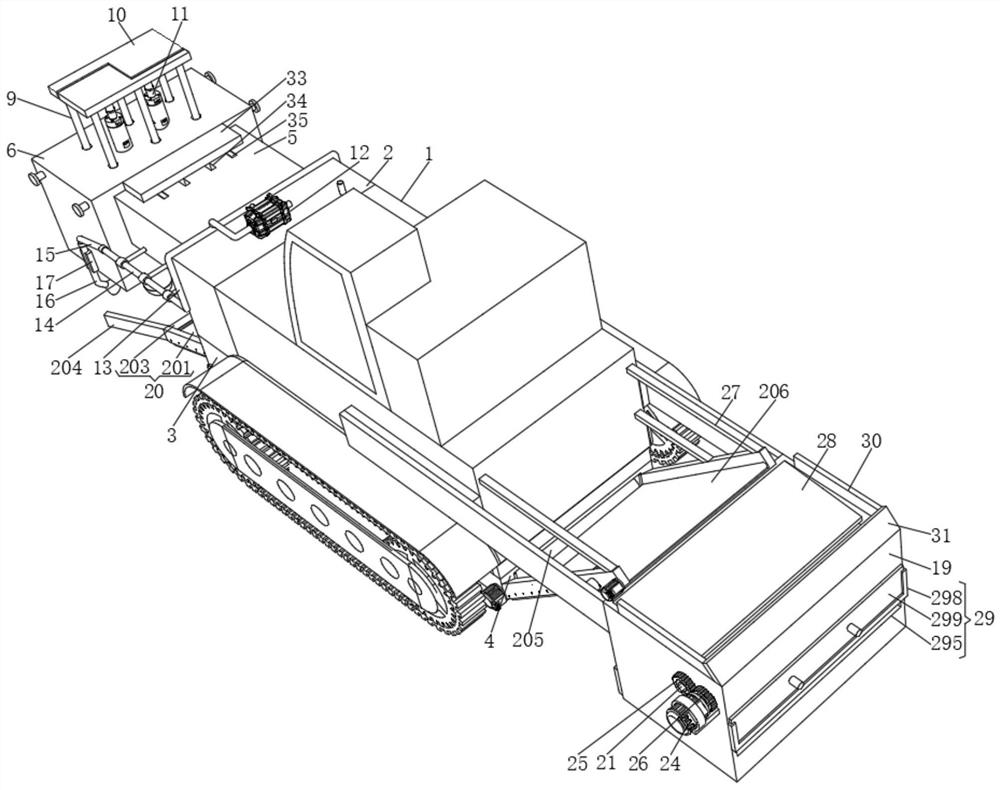
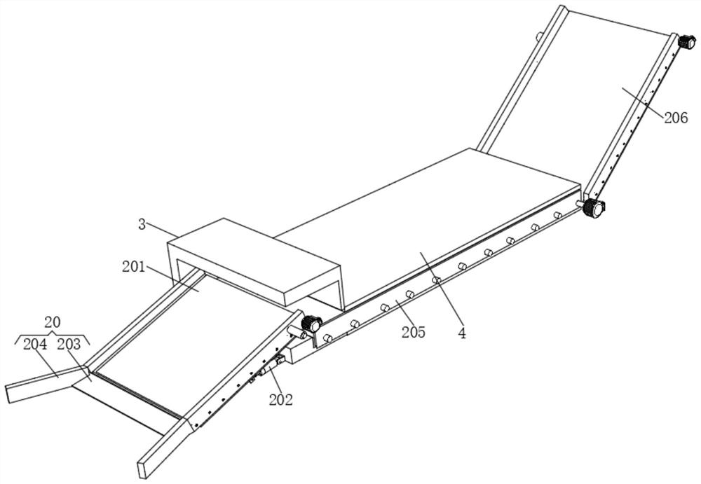
[0034] Such as Figure 1-6 The integrated system for concrete pavement crushing and treatment shown includes a pavement crusher body 1, a water tank 2 is fixedly connected to the top of one side of the road crusher body 1, a fixed frame 3 is fixedly connected to the bottom of the water tank 2, and the fixed frame 3 One side is fixedly connected to the road crusher body 1, the bottom of one side of the fixed frame 3 is fixedly connected with a support frame 4 and the support frame 4 is located at the bottom of the road crusher body 1, and the top side of the support frame 4 is fixedly connected through a connecting plate At the bottom of the road breaker body 1, the front and back of the road breaker body 1 are fixedly connected with a support plate 18, one side of the support plate 18 is fixedly connected with a box body 19, and the four sides of the bottom of the box body 19 are provided with universal The wheels can assist the movement of the box body 19 and support the box ...

Embodiment 2

[0045] This embodiment is a further improvement of the previous embodiment, such as Figure 1-6 As shown, an integrated system for concrete pavement crushing and treatment includes a pavement crusher body 1, a water tank 2 is fixedly connected to the top of one side of the road crusher body 1, a fixed frame 3 is fixedly connected to the bottom of the water tank 2 and the fixed frame 3 One side is fixedly connected to the road crusher body 1, the bottom of one side of the fixed frame 3 is fixedly connected with a support frame 4 and the support frame 4 is located at the bottom of the road crusher body 1, and the top side of the support frame 4 is fixedly connected through a connecting plate At the bottom of the road breaker body 1, the front and back of the road breaker body 1 are fixedly connected with a support plate 18, one side of the support plate 18 is fixedly connected with a box body 19, and the four sides of the bottom of the box body 19 are provided with universal The...


PUM


Abstract

The invention relates to a concrete pavement crushing treatment integrated system and belongs to the technical field of road engineering.The top of one side of a pavement crusher body is fixedly connected with a water tank, the bottom of the water tank is fixedly connected with a fixing frame, and one side of the fixing frame is fixedly connected to the pavement crusher body; a supporting frame is fixedly connected to the bottom of one side of the fixing frame and located at the bottom of the pavement crusher body, one side of the top of the supporting frame is fixedly connected to the bottom of the pavement crusher body through a connecting plate, and supporting plates are fixedly connected to the front face and the back face of the pavement crusher body correspondingly. According to the system, broken stones can be collected and smashed, classified collection can be directly conducted in the device according to the particle size, follow-up direct use is facilitated, the road surface on which the vehicle passes can be clean, meanwhile, the integrated assembly line operation of separation, screening and disposal is achieved, and the working efficiency of the device is improved.

Description

technical field [0001] The invention belongs to the technical field of road engineering and relates to an integrated system for concrete pavement crushing and treatment. Background technique [0002] Road engineering refers to the whole process of planning, design, construction, maintenance and management of roads and the engineering entities involved. In the upgrading process of road engineering, it is necessary to use the multi-hammer hydraulic concrete pavement crushing device to crush the concrete pavement in order to lay new pavement. [0003] However, the traditional multi-hammer hydraulic concrete pavement crushing device cannot collect the crushed gravel after crushing the concrete pavement, and cannot directly classify and collect the crushed stone according to the particle size in the crushing device, resulting in It cannot be used directly in the follow-up, and the car cannot be cleaned by walking. It is necessary for the user to use a sweeper to clean the gravel...

Claims


Application Information

Patent Timeline
IPC IPC(8): B02C21/00B02C1/00B02C4/02B02C23/10B02C23/14B07B1/04E01C23/12
CPCB02C21/00B02C1/005B02C4/02B02C23/10B02C23/14B07B1/04E01C23/12E01C23/122
Inventor 汪小林张铭黄轶郑晏华李申杰陈国祥张锡霖
Owner SHANGHAI NO 4 CONSTR
Why Eureka
Try Eureka