Carbon dioxide laser cutting machine rack with automatic feeding mechanism
A technology of laser cutting machine and carbon dioxide, which is applied in the direction of laser welding equipment, manufacturing tools, welding equipment, etc., can solve the problems of inability to improve work efficiency, manpower consumption, manual feeding, etc.
- Summary
- Abstract
- Description
- Claims
- Application Information
AI Technical Summary
Problems solved by technology
Method used
Image

Examples
Embodiment 1
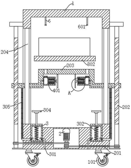
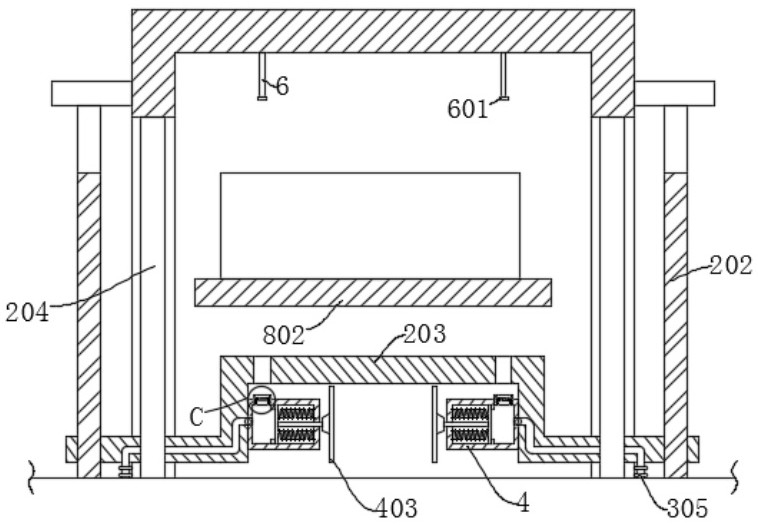
[0030] refer to Figure 1-7 , a carbon dioxide laser cutting machine frame with an automatic feeding mechanism, including a frame 1, and also includes: a support plate 203 assembled on the frame 1, and a sleeve 24 for clamping materials is installed on the support plate 203; The air pipe 5 is connected to the sleeve 2 4, the exhaust pipe 5 is provided with a sealing plate 504; the conductive sheet 2 602 is installed on the sealing plate 504, and the frame 1 is provided with a drive assembly for driving the support plate 203 to move; Connecting rod 2 6 is installed on the top inner wall of frame 1; conductive sheet 1 601 is installed on the top of connecting rod 2 6; electric telescopic rod 7 is installed on the inner wall of frame 1, and scraper 701 is installed at the output end of electric telescopic rod 7; The plate 802 is arranged under the scraper 701 , and the side wall of the frame 1 is provided with a driving part for driving the partition 802 to move.
[0031] The dr...
Embodiment 2
[0035] refer to Figure 1-7 , the frame of the carbon dioxide laser cutting machine with an automatic feeding mechanism is basically the same as that of Embodiment 1, and furthermore, the inner walls on both sides of the exhaust pipe 5 are equipped with limiting blocks 501, and the limiting blocks 501 and the sealing plate 504 are provided with The interlaced air outlets 505, the spring three 503 are connected between the sealing plate 504 and the exhaust pipe 5, and the spring two 402 is connected between the sleeve two 4 and the piston disc two 401.
[0036] Sliding rods 502 are installed on the inner walls of both sides of the exhaust pipe 5 , and the sealing plate 504 is slidably connected to the sliding rods 502 .
[0037] The driving part for driving the partition 802 to move includes a threaded rod 801 installed on the inner wall of the frame 1, and a motor 2 8 is installed on the outer wall of the frame 1, and the threaded rod 801 is fixedly connected with the output e...
Embodiment 3
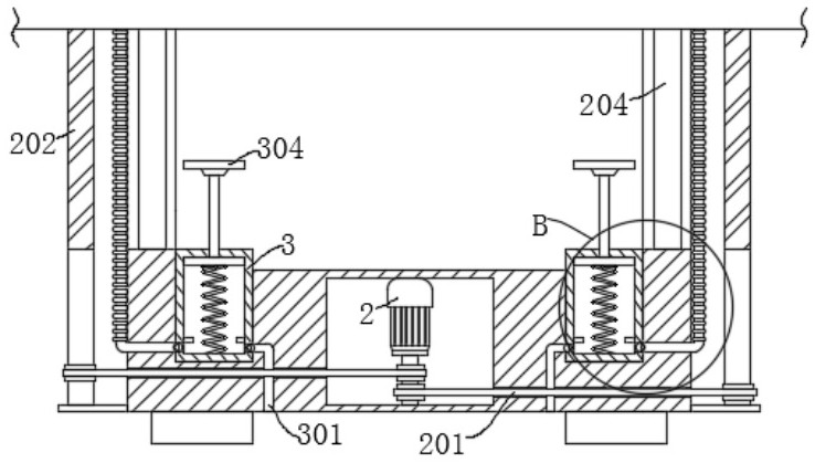
[0045] refer to Figure 1-7 , the frame of the carbon dioxide laser cutting machine with an automatic feeding mechanism is basically the same as that of Embodiment 1, and furthermore, the inner walls on both sides of the frame 1 are provided with a guide rod-204, and the support plate 203 is slidably connected to the guide rod-204; Since the support plate 203 is slidably connected to the guide rod one 204 and is threadedly connected with the screw mandrel 202, when the screw rod 202 drives the support plate 203 to move up and down, the support plate 203 is limited by the guide rod one 204, so that the support plate 203 moves smoothly on frame 1.
PUM
 Abstract
Description
Claims
Application Information
 - R&D Engineer
- R&D Manager
- IP Professional
- Industry Leading Data Capabilities
- Powerful AI technology
- Patent DNA Extraction
Browse by: Latest US Patents, China's latest patents, Technical Efficacy Thesaurus, Application Domain, Technology Topic.
© 2024 PatSnap. All rights reserved.Legal|Privacy policy|Modern Slavery Act Transparency Statement|Sitemap