Method for automatically assembling gear reducer

A technology of gear reducer and gear shaft, which is applied in the direction of assembly machine, workpiece clamping device, metal processing equipment, etc., can solve the problems of increased manufacturing cost, large labor consumption, slow manual assembly speed, etc., and achieves strong assembly stability, High degree of automation and good product uniformity

Active Publication Date: 2022-02-11
东莞市川正机电科技有限公司 +1
View PDF3 Cites 0 Cited by
  • Summary
  • Abstract
  • Description
  • Claims
  • Application Information

AI Technical Summary

Problems solved by technology

However, the manual assembly of the gear reducer has two major technical defects
One is that manual assembly requires extremely high experience of operators, and there are often wrong and missing installations during assembly, resulting in a high rate of defective products.
The second is tha

Method used


Image

  • Method for automatically assembling gear reducer
  • Method for automatically assembling gear reducer
  • Method for automatically assembling gear reducer

Examples


Example Embodiment

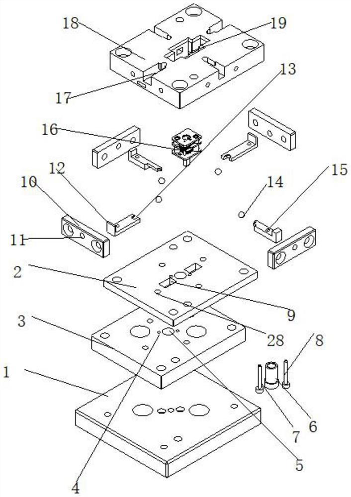
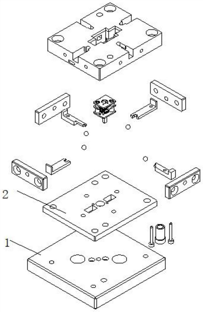
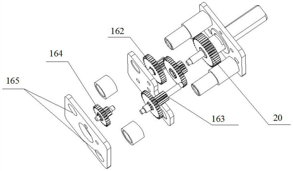
[0051] Embodiment 1: In combination with all the accompanying drawings; an automatic assembly tool for a gear reducer, characterized in that the tool includes a base plate 1 on which a fixing cylinder 6 and two fixing columns are fixed, and the two fixing columns are fixed columns one 7 and two fixed columns 8; the fixed cylinder 6 and the two fixed columns pass through the corresponding holes on the assembly reference plate 2, and also include a top plate 18, which is fixed on the assembly reference plate 2 and the bottom plate 1 by bolts; on the top plate 18 The middle part contains the operation hole 19, and the fixed cylinder 6 and the two fixed columns are located in the operation hole 19 facing upwards. The output shaft 20 of the workpiece 16 can be inserted downward into the fixed cylinder 6. The workpiece contains a workpiece positioning hole 165, and the fixed columns can be inserted into the fixed cylinder 6. The entire workpiece can be positioned in the workpiece pos...

Example Embodiment

[0053] Embodiment 2: As a further improved solution or a side-by-side solution or an optional independent solution, the workpiece 16 is a gear reducer; the through hole in the middle of the fixed cylinder 6 is used to avoid the output shaft 20, which is suitable for different lengths and outer dimensions. The output shaft 20 of diameter, flat position. The substantive technical effect and the realization process of the technical solution here are as follows: the gear reducer of this patent is the preferred assembly object, in fact, it can also be assembled with a multi-axis system, and similar solutions are also within the scope of protection of this patent Inside.

Example Embodiment

[0054] Embodiment 3: As a further improved solution or a side-by-side solution or an optional independent solution, more than one ball 14 is included on the assembly reference plate 2, and the lower part of the ball 14 is located in the ball groove 28. 14 slide block, the end of the slide block includes a push plate arc section 13; the push plate arc section 13 can relatively locate the gear shaft; the slide block can move in the moving groove 17. The substantive technical effect and the realization process of the technical solution here are as follows: refer to the method of the second solution, which is mainly for positioning and straightening the shaft.


PUM


Abstract

The invention relates to the field of manufacturing and assembling of gear reducers, in particular to a method for automatically assembling a gear reducer. The method comprises the steps that: firstly, a support of a workpiece (16) is placed in an operation hole (19), at the moment, an output shaft (20) of the workpiece (16) is downwards inserted into a fixing cylinder (6), and a fixing column can be inserted into a workpiece positioning hole (165) so that the whole workpiece can be positioned; secondly, gear shafts are inserted, after the gear shafts are inserted, a side air cylinder (22) is started, an air cylinder shaft of the side air cylinder (22) is pushed forwards so that a sliding block can move forwards, and the upper portion of a ball (14) is matched with the lower portion of a sliding block through hole (15) in the sliding block so that relative positioning can be achieved; at the moment, a push plate arc-shaped section (13) of the sliding block is in advanced contact with the gear shafts, so that the gear shafts can be prevented from falling down; a plurality of the gear shafts are placed in sequence, and overall assembly is achieved; and after assembly is completed, the side air cylinder (22) is started to withdraw the air cylinder shaft.

Description

technical field [0001] The invention relates to the field of manufacture and assembly of gear reducers, in particular to a method for automatic assembly of gear reducers. Background technique [0002] A gear reducer is a device that reduces the speed of the motor and increases the output torque. It is usually driven by multi-stage gears. It is widely used in industrial product drives, intelligent robots, intelligent door locks, instruments and meters, medical equipment, electric household appliances, Audio and video, office automation and automobiles and other fields. With the continuous development of the economy, there are more and more automation and intelligent products, and the requirements for the production capacity and quality of gear reducers are getting higher and higher. The production and assembly of traditional gear reducers are currently mainly operated by hand. However, manual assembly of gear reducers has two major technical defects. One is that manual ass...

Claims


Application Information

Patent Timeline
IPC IPC(8): B23P21/00B25B11/02
CPCB23P21/00B25B11/02
Inventor 罗飞龙韩占龙张小平赵耕
Owner 东莞市川正机电科技有限公司
Why Eureka
Try Eureka