
Foundation pit drainage device and construction method thereof

A technology for drainage devices and foundation pits, which is used in infrastructure engineering, excavation, construction, etc., can solve the problems of not being very flat at the bottom of the foundation pit, unable to discharge water, and poor drainage effect, so as to improve the drainage effect and shorten the construction. Cycle time, the effect of improving construction efficiency

Active Publication Date: 2022-02-11
浙江银晨建设有限公司
View PDF4 Cites 1 Cited by
  • Summary
  • Abstract
  • Description
  • Claims
  • Application Information

AI Technical Summary

Problems solved by technology

[0003]In related technologies, water pumps are generally used for water pumping, but the bottom of the foundation pit is not very smooth, and there are generally some low-lying or depressions at the bottom of the foundation pit, so when After the water pump pumps out most of the accumulated water, there will still be some small puddles and accumulated water in the ditch at the bottom of the foundation pit that cannot be discharged by the water pump
[0004] Regarding the above-mentioned related technologies, the inventor believes that when using a pump to drain water in the related technologies, the small puddles at the bottom of the foundation pit and the accumulated water in the ditch cannot be discharged , so there is a defect that the drainage effect is not good

Method used


Image

  • Foundation pit drainage device and construction method thereof
  • Foundation pit drainage device and construction method thereof
  • Foundation pit drainage device and construction method thereof

Examples


Embodiment Construction

[0038] The following is attached Figure 1-5 The application is described in further detail.

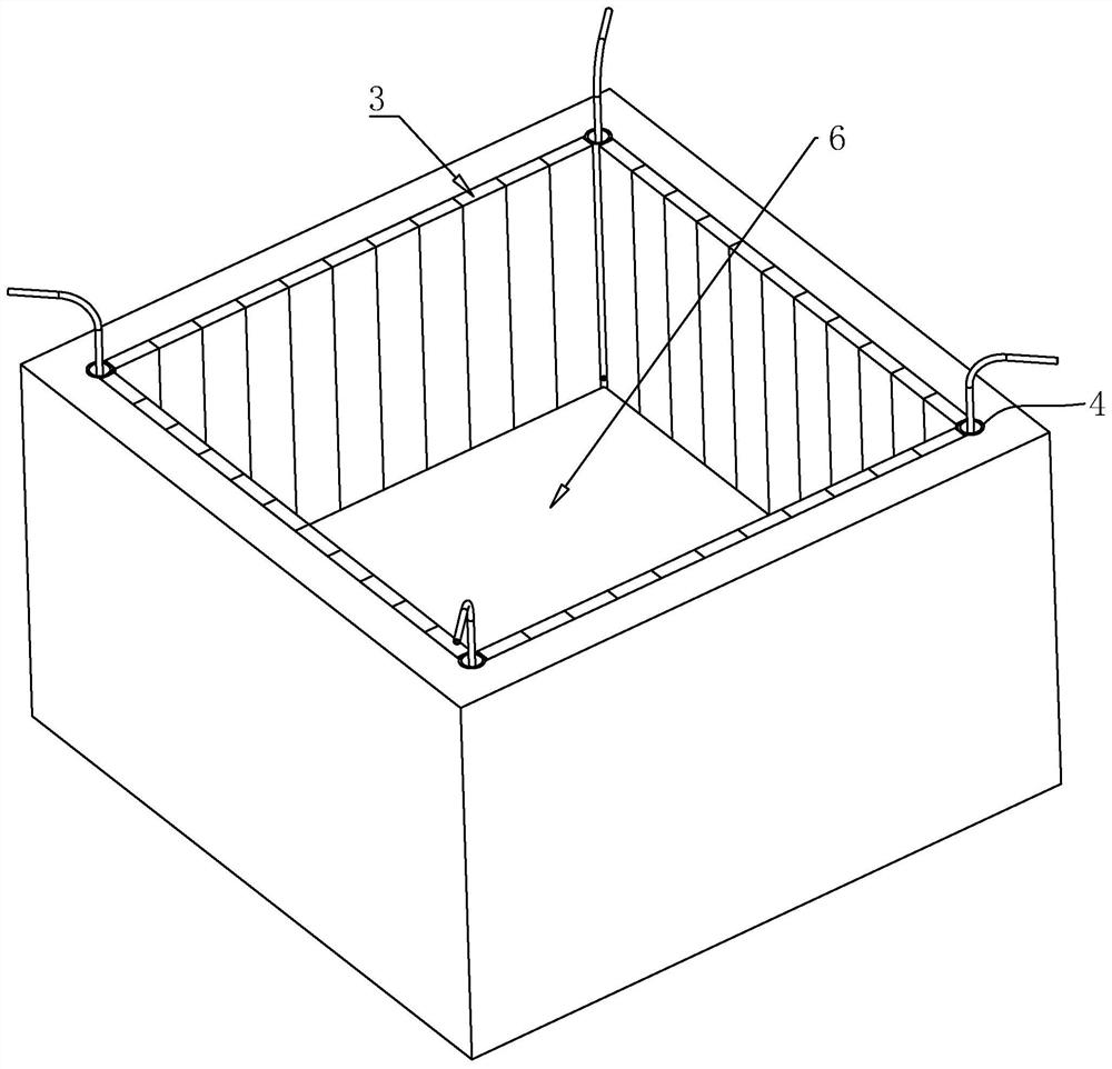
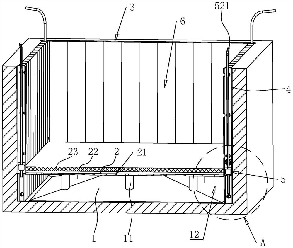
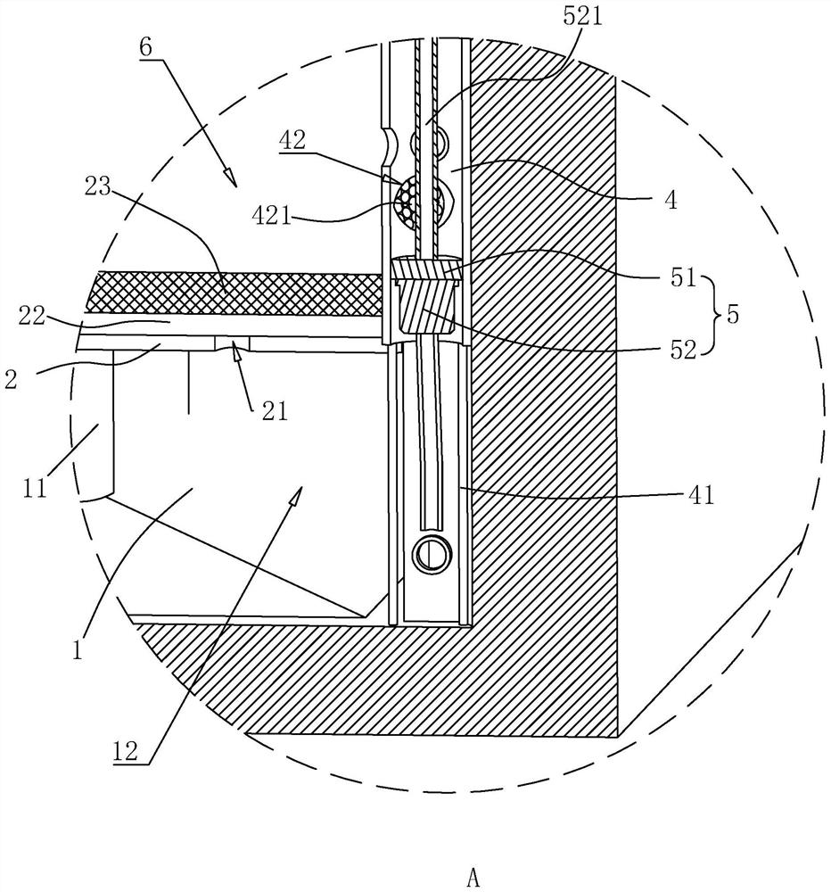
[0039] The embodiment of the present application discloses a foundation pit drainage device. refer to figure 1 and figure 2 , a drainage device for a foundation pit 6 includes a water collecting platform 1 , a permeable plate 2 , a support plate 3 , a water collecting pipe 4 and a drainage assembly 5 .

[0040] refer to figure 1 and figure 2 The water collecting platform 1 is poured with concrete at the bottom of the foundation pit 6, the upper surface of the water collecting platform 1 is inclined downward along the center towards the edge of the foundation pit 6, and the edge of the water collecting platform 1 is on the same plane as the bottom of the foundation pit 6. The water collection platform 1 is in the shape of a quadrangular pyramid as a whole, and a plurality of uniformly distributed reinforcing ribs 11 are pre-embedded in the water collection platform 1 .

[0041...


PUM


Abstract

The invention relates to a foundation pit drainage device and a construction method thereof, and relates to the technical field of building construction. The foundation pit drainage device comprises a water collecting table, a permeable plate, a water collecting pipe and a drainage assembly, the water collecting table is located at the bottom of a foundation pit, the upper surface of the water collecting table is obliquely arranged downwards in the direction close to the edge of the foundation pit along the center, the permeable plate is located above the water collecting table, a water collecting well is formed between the permeable plate and the water collecting table, and multiple water-permeable holes are formed in the permeable plate; the water-permeable holes are communicated with the water-collecting well, the water-collecting pipes are vertically arranged at the corners of the foundation pit respectively, one end of each water-collecting pipe is communicated with the water-collecting well, and the drainage assembly is used for draining rainwater in the water-collecting well. During working, accumulated water in a small water pit and a ditch at the bottom of a foundation pit leaks into the water collecting well through the water permeable plate, and then the accumulated water collected in the water collecting well is drained through the drainage assembly. The foundation pit drainage device has the advantages of being high in construction efficiency and good in drainage effect.

Description

technical field [0001] The present application relates to the technical field of building construction, in particular to a foundation pit drainage device and a construction method thereof. Background technique [0002] Foundation pit refers to the space below the ground excavated for the construction of building foundation and basement. Due to the long construction process of the foundation pit, and the subsequent building construction process is also very long, if it encounters rainy weather during the construction process, a large amount of water will be accumulated in the foundation pit, which will have a great impact on the construction, so After the construction of the foundation pit, it is necessary to do a good job of drainage. [0003] In related technologies, water pumps are generally used for pumping water, but the bottom of the foundation pit is not very smooth, and there are generally some low-lying or depressions at the bottom of the foundation pit, so when the...

Claims


Application Information

Patent Timeline
Patent Type & Authority Applications(China)
IPC IPC(8): E02D19/10E02D17/04E02D19/22
CPCE02D19/10E02D17/04E02D19/22
Inventor 郭立郑箜琳李尚君申屠盼盼龚计宽王宇豪刘明雷
Owner 浙江银晨建设有限公司
Learn More