
Method and system for measuring incoming cloud distribution in mirror field

A measurement method and technology of a measurement system, which are applied in the measurement method and system field of incoming cloud distribution in the mirror field, can solve the problems of inability to accurately predict the distribution of DNI and reduce the performance of the mirror field when the cloud is coming, so as to improve the utilization rate of optical resources, Optimizing the comprehensive design of the mirror field and reducing the cost

Pending Publication Date: 2022-02-11
ZHEJIANG SUPCON SOLAR TECHNOLOGY CO LTD
View PDF10 Cites 0 Cited by
  • Summary
  • Abstract
  • Description
  • Claims
  • Application Information

AI Technical Summary

Problems solved by technology

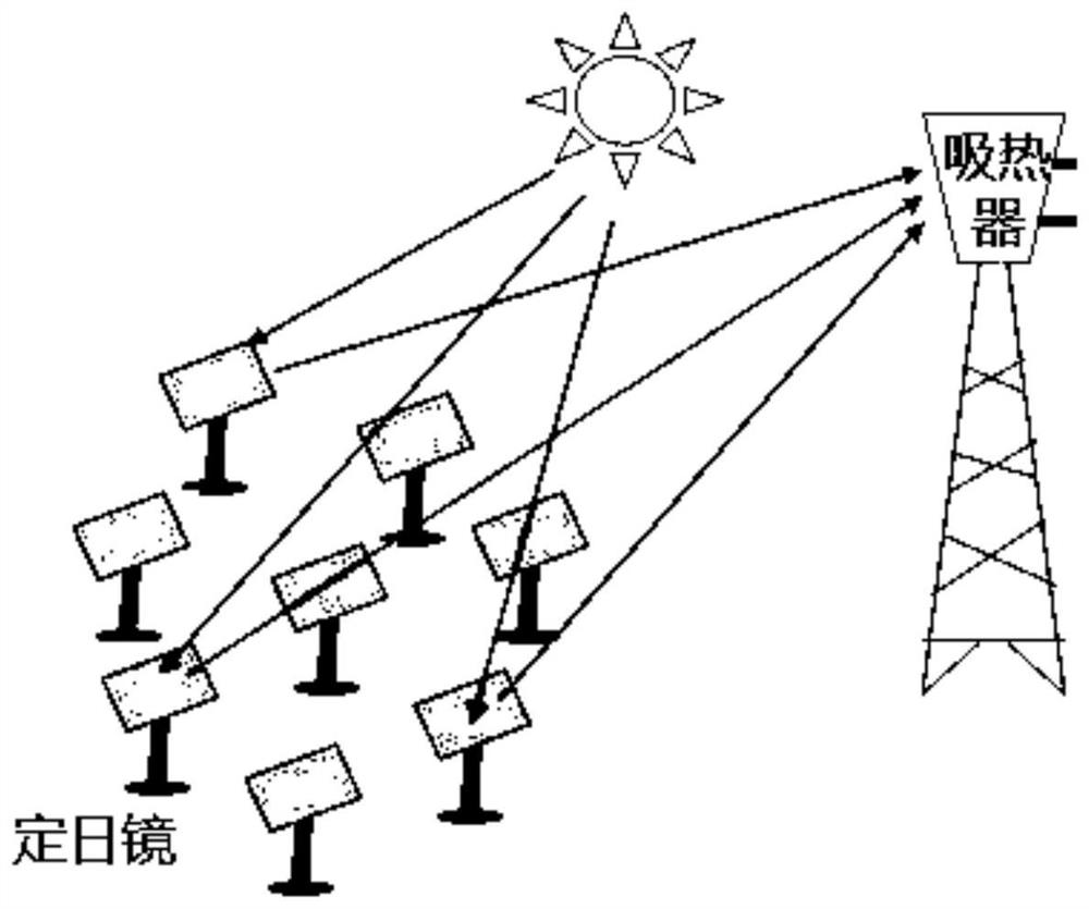
Since it is impossible to accurately predict the distribution of DNI in the whole field when the cloud is coming, and at the same time, it cannot bear the serious consequences of the temperature rise and temperature drop overload of the heat absorber panel due to the energy fluctuation of the mirror field. Generally, commercial power stations will choose to actively reduce the mirrors in operation when they come to the cloud. From the quantity to the absolute safety range, this conservative operation strategy greatly reduces the performance of the mirror field when coming to the cloud

Method used


Image

  • Method and system for measuring incoming cloud distribution in mirror field
  • Method and system for measuring incoming cloud distribution in mirror field
  • Method and system for measuring incoming cloud distribution in mirror field

Examples


Embodiment Construction

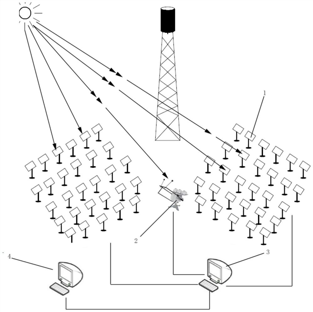
[0055] In order to more clearly illustrate the embodiments of the present invention or the technical solutions in the prior art, the specific implementation manners of the present invention will be described below with reference to the accompanying drawings. Obviously, the accompanying drawings in the following description are only some embodiments of the present invention, and those skilled in the art can obtain other accompanying drawings based on these drawings and obtain other implementations.

[0056] In order to make the drawing concise, each drawing only schematically shows the parts related to the present invention, and they do not represent the actual structure of the product. In addition, to make the drawings concise and easy to understand, in some drawings, only one of the components having the same structure or function is schematically shown, or only one of them is marked. Herein, "a" not only means "only one", but also means "more than one".

[0057] A method a...


PUM


Abstract

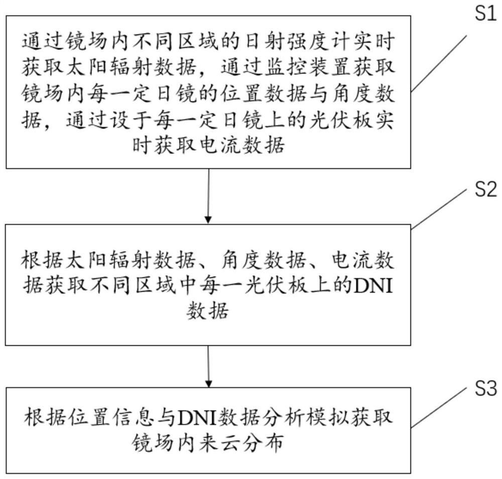
The invention discloses a method and system for measuring incoming cloud distribution in a mirror field. The method comprises the steps of: S1, obtaining solar radiation data in real time through solar radiation intensity meters in different regions in the mirror field, and obtaining the position data and angle data of each heliostat in the mirror field through a monitoring device, acquiring current data in real time through a photovoltaic panel arranged on each heliostat; S2, acquiring DNI data on each photovoltaic panel in the different regions according to the solar radiation data, the angle data and the current data; and S3, according to the position information and the DNI data, performing analysis and simulation to obtain incoming cloud distribution in the mirror field. According to the method and system for measuring the incoming cloud distribution in the mirror field of the invention, the measurement of the incoming cloud distribution in the whole mirror field can be completed by combining solar radiation values measured by a few solar radiation intensity meters with the current data of the photovoltaic panels on the heliostats, so that the cost of the measurement of the incoming cloud distribution in the mirror field is reduced, real-time measurement can be realized, and therefore, the control of the heliostats in the mirror field is effectively optimized, and the utilization rate of light resources is greatly improved while safe operation of a whole power station is ensured.

Description

technical field [0001] The invention belongs to the technical field of solar thermal power generation, and in particular relates to a method and system for measuring the distribution of incoming clouds in a mirror field. Background technique [0002] While the economy continues to develop, energy is increasingly in short supply, traditional non-renewable energy is increasingly exhausted, and economic development is increasingly constrained by the development and utilization of energy. The utilization of renewable energy has attracted widespread attention, especially the utilization of solar energy has attracted more attention from the world. [0003] Solar thermal power generation is a major way of utilizing solar energy at present. The current solar thermal power generation can be divided into (1) tower solar thermal power generation; (2) trough solar thermal power generation; (3) dish solar thermal power generation according to the way of solar energy collection. [0004]...

Claims


Application Information

Patent Timeline
IPC IPC(8): F24S50/80F24S20/20F24S23/77
CPCF24S50/80F24S23/77F24S20/20F24S2023/87Y02E10/40
Inventor 韩梦天薛刚强刘志娟谈双单
Owner ZHEJIANG SUPCON SOLAR TECHNOLOGY CO LTD
Learn More