
Medical instrument dryer

A technology of medical devices and dryers, which is applied in the direction of drying solid materials, dry goods processing, local agitation dryers, etc. It can solve the problems of incomplete guarantee of disinfection cloth, rust on the surface of the device, and contamination of the device, so as to avoid accidents Effects of electric shock, improved usability, and improved safety

Pending Publication Date: 2022-02-11
周圣宜
View PDF5 Cites 0 Cited by
  • Summary
  • Abstract
  • Description
  • Claims
  • Application Information

AI Technical Summary

Problems solved by technology

[0002] Medical devices refer to instruments, equipment, utensils, in vitro diagnostic reagents and calibrators, materials, and other similar or related items that are used directly or indirectly on the human body, the main purpose of which is the diagnosis of diseases; In the current technology, medical instruments need to be disinfected and cleaned after use to ensure that they will not cause secondary harm to the patient in the next use. At present, most of the disinfection methods for medical instruments are manually or corresponding devices are used to wash and disinfect with liquid. , but after the liquid is rinsed, the liquid on the instrument needs to be dried. The current method is to use a sterile cloth to dry or dry it directly. It may cause secondary pollution of the sterilized instruments, and the bacteria in the air will also float on the surface of the instrument in the air-drying method, causing secondary pollution. At the same time, the drying method will also cause rust on the surface of the instrument happened

Method used


Image

  • Medical instrument dryer
  • Medical instrument dryer
  • Medical instrument dryer

Examples


Embodiment

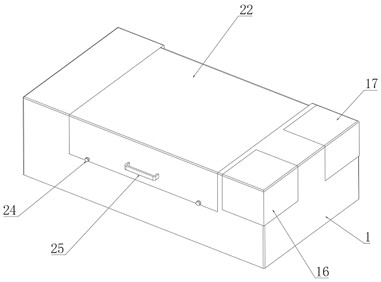
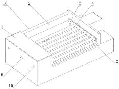
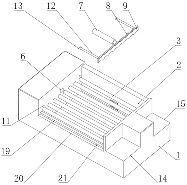
[0025] see Figure 1-4 , the present invention provides the following technical solutions: a dryer for medical equipment, including a dryer body 1, a storage tank 2 is provided in the middle of the top of the dryer body 1, and insulating support rollers 3 are equidistantly installed in the middle of both sides of the inner wall of the storage tank 2, A first insulating plate 4 is installed in the middle of one side of the inner wall of the storage tank 2 close to the insulating support roller 3, a first electrode plate 5 is installed in the middle of one side of the first insulating plate 4, and a fixing hole 6 is opened in the middle of the other side of the inner wall of the storage tank 2 A telescopic cylinder 7 is installed inside the fixing hole 6, a second insulating plate 8 is installed at the push rod end of the telescopic cylinder 7, and a second electrode plate 9 is installed in the middle of one side of the second insulating plate 8;

[0026] A limiting groove 10 is...


PUM


Abstract

The invention belongs to the technical field of medical instrument drying, and particularly relates to a medical instrument dryer which comprises a dryer body, a storage groove is formed in the middle of the top end of the dryer body, and insulating supporting rollers are equidistantly installed in the middles of the two sides of the inner wall of the storage groove. A first insulating plate is mounted in the middle, close to the insulating supporting roller, of one side of the inner wall of the storage groove, and a first electrode plate is mounted in the middle of one side of the first insulating plate. According to the medical instrument dryer, through use of a telescopic air cylinder, a second insulating plate and a second electrode plate, the position of medical equipment can be adjusted, the use performance of the dryer can be improved, the dryer can conveniently dry the medical equipment of different sizes, through use of an exhaust groove, exhaust holes and an exhaust fan, water vapor in the dryer can be exhausted. Through cooperative use of a first electrode plate, the second electrode plate, a controller and a transformer, medical instruments can be dried, the drying difficulty of the medical instruments can be reduced, and meanwhile the drying rate of the medical instruments can be increased.

Description

technical field [0001] The invention relates to the technical field of medical equipment, in particular to a dryer for medical equipment. Background technique [0002] Medical devices refer to instruments, equipment, utensils, in vitro diagnostic reagents and calibrators, materials, and other similar or related items that are used directly or indirectly on the human body, the main purpose of which is the diagnosis of diseases; In the current technology, medical devices need to be disinfected and cleaned after use to ensure that they will not cause secondary harm to the patient in the next use. At present, most of the disinfection methods for medical devices are manual or corresponding devices using liquid flushing and disinfection. , but after the liquid is rinsed, the liquid on the instrument needs to be dried. The current method is to use a sterile cloth to dry or directly dry it. The method of using a sterile cloth cannot completely guarantee the cleanliness of the steril...

Claims


Application Information

Patent Timeline
IPC IPC(8): F26B9/06F26B23/04F26B25/00
CPCF26B9/06F26B23/04F26B25/003F26B25/005F26B25/008
Inventor 周圣宜
Owner 周圣宜
Learn More