Visual test device for simulating grouting of grouting holes in different positions of duct piece and test method thereof

A technology of test device and grouting hole, which is applied in the field of visual test device, can solve the problems of unsatisfactory visualization effect, high test cost, limited research scope, etc., and achieve the effect of shortening test cycle, high data resolution and ensuring effectiveness

Pending Publication Date: 2022-02-11
ZHEJIANG UNIV OF TECH
View PDF3 Cites 1 Cited by
  • Summary
  • Abstract
  • Description
  • Claims
  • Application Information

AI Technical Summary

Problems solved by technology

[0010] To sum up, the current technical problems of shield grouting related technologies and test devices include: high test cost, unsatisfactory visualization effect, limited research scope, etc. question

Method used


Image

  • Visual test device for simulating grouting of grouting holes in different positions of duct piece and test method thereof
  • Visual test device for simulating grouting of grouting holes in different positions of duct piece and test method thereof
  • Visual test device for simulating grouting of grouting holes in different positions of duct piece and test method thereof

Examples


Embodiment Construction

[0055] The present invention will be described in further detail below in conjunction with the accompanying drawings and embodiments. Wherein the same components are denoted by the same reference numerals. It should be noted that the words "front", "rear", "left", "right", "upper" and "lower" used in the following description refer to the directions in the drawings, and the words "bottom" and "top "Face", "inner" and "outer" refer to directions toward or away from, respectively, the geometric center of a particular component.

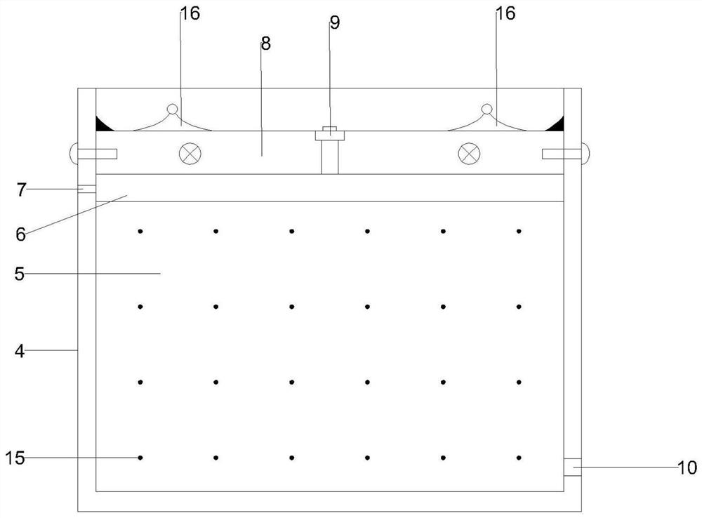
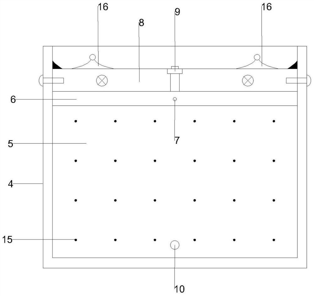
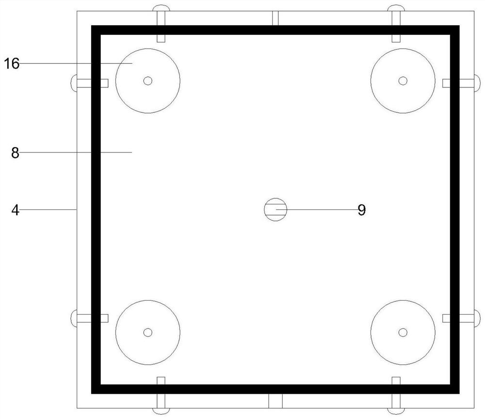
[0056] refer to Figure 1-5 As shown, the visual test device for simulating grouting hole grouting at different positions of the segment provided in Embodiment 1 of the present invention includes a double-liquid grouting system, a model box system, a support system, and a data acquisition and processing system;

[0057] Double-liquid grouting system: including cement slurry storage tank 1 and water glass slurry storage tank 2, cement slurry storage ta...


PUM


Abstract

The invention discloses a visual test device for simulating grouting of grouting holes in different positions of a duct piece. The visual test device comprises a double-liquid grouting system, a model box system, a support system and a data acquisition and processing system. The invention further provides a test method of the visual test device for simulating grouting of the grouting holes in the different positions of the duct piece. The device has the following technical effects: 1, local segment grouting simulation can be realized, the size of the matched model box is small, and less transparent soil, cement slurry and water glass slurry are required by the test, so that the test cost can be saved, and the test period can be shortened; 2, the transverse and longitudinal side lengths of a model box are not large, so that the visual advantage of the transparent device cannot be influenced by too long perspective depth; 3, the device is provided with a rotating bracket, so that the grouting condition of the grouting hole at any position on the segment ring of the actual engineering can be simulated; and 4, a matched test image measurement technology is high in precision, soil body motion information in a specified area range can be measured, and long-time continuous measurement can be carried out.

Description

technical field [0001] The invention relates to a visual test device for simulating the grouting of grouting holes in different positions of a segment. Background technique [0002] At present, urban tunnel construction widely adopts the shield tunneling method with strong adaptability to geological conditions and fast construction speed. This method can greatly alleviate the urban traffic congestion caused during the construction period. [0003] In the construction process of shield tunneling, surface settlement is the data that needs to be detected mainly, and the data is affected by many factors. [0004] Among them, the construction effect of shield grouting has a significant impact on surface settlement. Because during the advancement of the shield machine, the shield tail casing will be separated from the assembled segments, and the original position of the shield tail casing will also form a thin-walled ring-shaped gap, and the segments will also be in a certain p...

Claims


Application Information

Patent Timeline
Patent Type & Authority Applications(China)
IPC IPC(8): G01N33/38
CPCG01N33/383
Inventor 徐山琳曹宏涛孙宏磊沈梦芬伍婷玉潘晓东朱彦臻
Owner ZHEJIANG UNIV OF TECH
Why Eureka
Try Eureka