Insulating skin fixed-length removing machine for wire processing

A technology for wire processing and insulation, which is applied in the field of fixed-length insulation removal machines for wire processing, which can solve problems such as low work efficiency, danger, and fire hazards, and achieve the effects of smooth wire movement, high work efficiency, and avoidance of deviation

Pending Publication Date: 2022-02-11
鹰潭申江科技有限公司
View PDF0 Cites 0 Cited by
  • Summary
  • Abstract
  • Description
  • Claims
  • Application Information

AI Technical Summary

Problems solved by technology

[0004] In order to overcome the shortcomings of using electrician pliers to remove, it is laborious, the work efficiency is low, and it is easy to cause open flames on the insulation skin, causing fires, which is relatively dangerous. , saves time and effort, high work efficiency, and is not easy to cause fire. Insulation fixed-length removal machine for wire processing

Method used


Image

  • Insulating skin fixed-length removing machine for wire processing
  • Insulating skin fixed-length removing machine for wire processing
  • Insulating skin fixed-length removing machine for wire processing

Examples


Embodiment 1

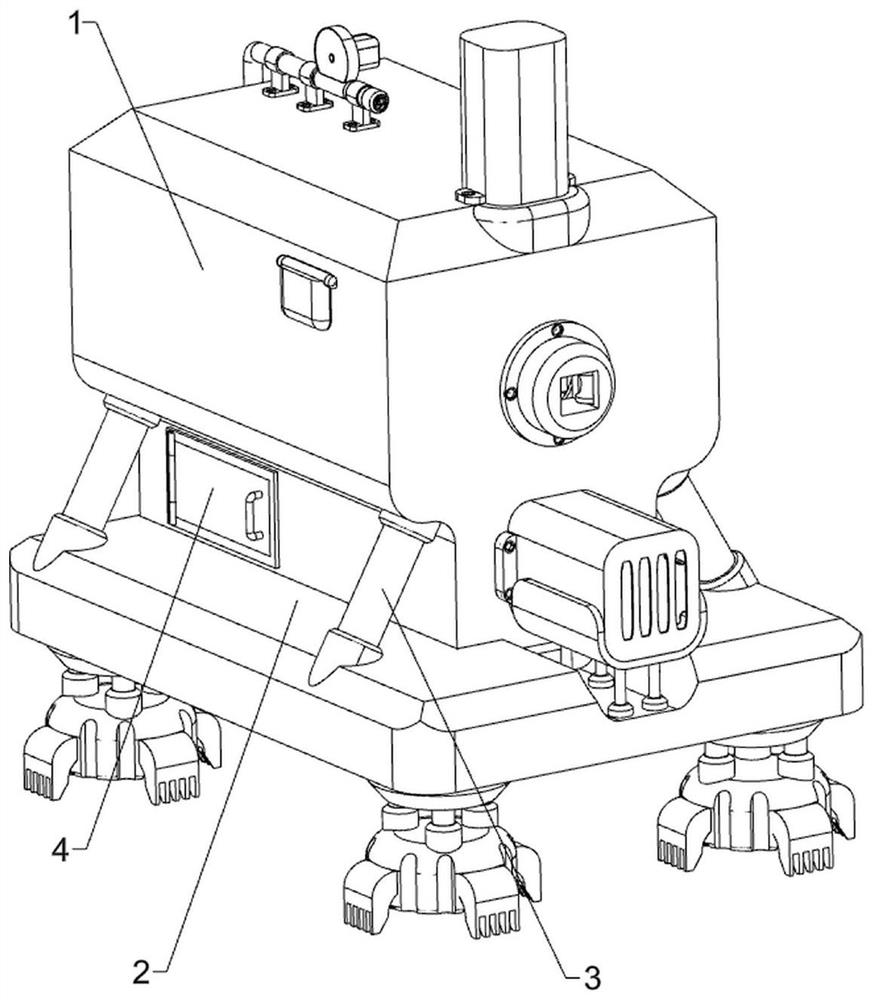
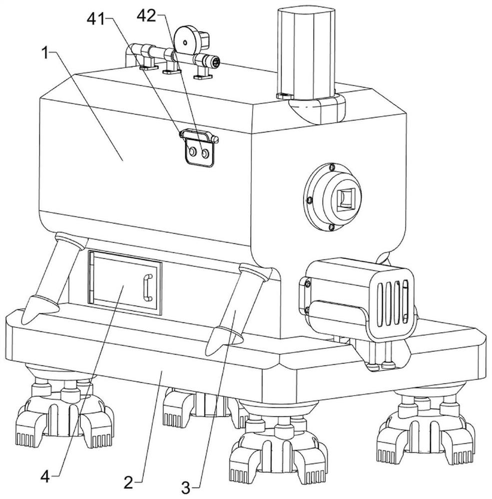
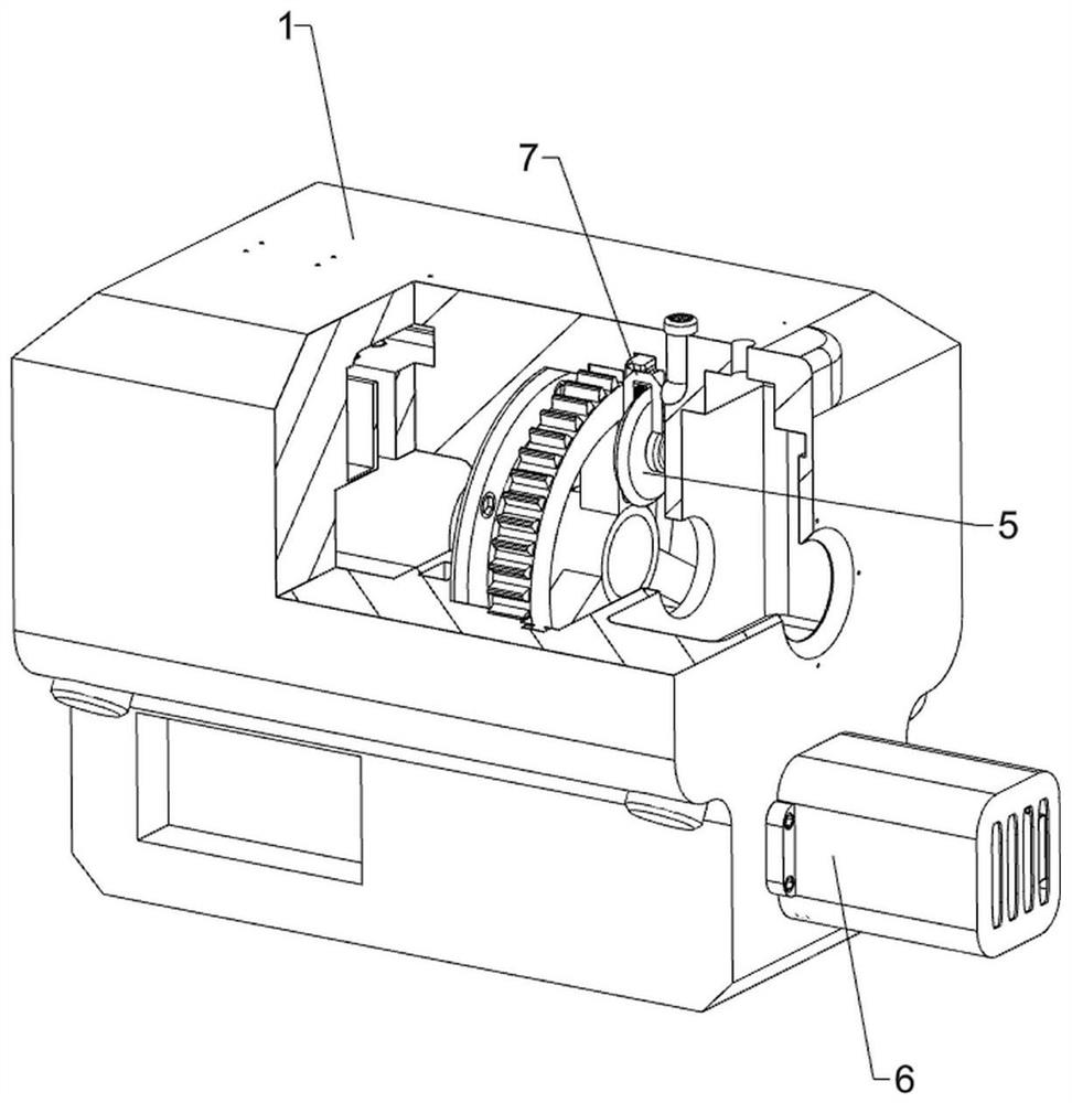
[0039] A kind of insulating skin fixed-length removing machine for electric wire processing, such as Figure 1-Figure 7 As shown, it includes a protective bottom box 1, a support base plate 2, a support column 3, a start button 41, a reset button 42, a separation cutter 5, a driving mechanism 6 and a cutting mechanism 7, and the bottom of the protective bottom box 1 is fixedly connected with a support base plate 2 , the top of the support base plate 2 is fixedly connected with four support columns 3 at intervals, the support columns 3 are connected with the protective bottom box 1, and the front part of the left side surface of the protective bottom box 1 is fixedly connected with a start button 41 and a reset button 42, and the reset button 42 is located at On the front side of the start button 41, the protective bottom box 1 is provided with a driving mechanism 6, and a cutting mechanism 7 is arranged between the driving mechanism 6 and the protective bottom box 1. The cuttin...

Embodiment 2

[0044] On the basis of Example 1, such as Figure 7-Figure 13 As shown, a positioning mechanism 8 is also included, and the positioning mechanism 8 includes a second installation bottom box 81, an electric push rod 82, an arched connecting plate 83, a positioning plate 84, a positioning column 85, a rubber bottom block 86, a photoelectric sensor 87, The buffer bottom block 88, the second return spring 89 and the second pressure sensor 810, the second installation bottom box 81 is fixedly connected to the front middle side of the outer top of the protective bottom box 1, and the electric push rod 82 is fixedly connected to the inside of the second installation bottom box 81 , the electric push rod 82 telescopic rod passes through the protective bottom box 1, the electric push rod 82 telescopic rod is connected with an arched connecting plate 83, and the middle of the front part of the protective bottom box 1 is fixedly connected with a rubber bottom block 86, and the rubber bott...

Embodiment 3

[0049] On the basis of embodiment 1 and embodiment, as Figure 7 , Figure 14 , Figure 15 , Figure 16 and Figure 17 As shown, a blowing mechanism 10 is also included, and the blowing mechanism 10 includes a blanking ramp 101, an installation top block 102, an air intake pump 103, a telescopic duct 104, a limit top plate 105, a lifting installation plate 106, and a driving roller 107 , gas guide inclined pipe 108, positioning underframe 109, the fifth return spring 1010 and the third pressure sensor 1011, the middle part of the back side of the protective bottom box 1 is fixedly connected with a blanking ramp 101, and the rear side of the top of the protective bottom box 1 is separated by three A top block 102 is installed, and a telescopic conduit 104 is arranged between the tops of the three top blocks 102. The telescopic conduit 104 passes through the protective bottom box 1. The front portion of the telescopic conduit 104 is connected with an intake pump 103, and the ...


PUM


Abstract

The invention relates to a removing machine, in particular to an insulating skin fixed-length removing machine for wire processing. The insulating skin fixed-length removing machine for wire processing is convenient for people to remove the insulating skin of each wire, time-saving, labor-saving, high in working efficiency and not easy to cause fire hazards. The insulating skin fixed-length removing machine for wire processing comprises a protective bottom box, a supporting bottom plate and supporting columns, wherein the supporting bottom plate is fixedly connected to the bottom of the protective bottom box, the four supporting columns are fixedly connected to the top of the supporting bottom plate at intervals, and the supporting columns are connected with the protective bottom box. The wire is pulled to be inserted into the protective bottom box, a servo motor is started to rotate forwards to drive a driving shaft to rotate forwards, then, a separation cutter moves inwards to make contact with the surface of the wire, a heating module operates to transmit heat energy to the separation cutter, and the separation cutter rotates backwards and moves inwards to cut the insulating skin of the wire, so that people can conveniently remove the insulating skin of the wire, time and labor are saved, working efficiency is high, and fire disasters are not prone to being caused.

Description

technical field [0001] The invention relates to a removing machine, in particular to a fixed-length insulating skin removing machine for electric wire processing. Background technique [0002] When wiring the wires, it is necessary to remove the insulation at both ends of the wires. The existing insulation removal of the wires is to use electrician pliers to remove the insulation. Although the insulation can be removed in this way, it is laborious and the work efficiency is still low. , Some also need to use a lighter when removing the insulation of the wire, which will easily cause the insulation to generate an open flame, and the open flame will drop on the plastic impurities on the ground, which is easy to cause a fire and is more dangerous. [0003] Therefore, need to design a kind of convenient people to remove the wire insulation, save time and effort, work efficiency is high, and the insulation skin fixed-length removal machine for electric wire processing that is dif...

Claims


Application Information

Patent Timeline
IPC IPC(8): H02G1/12B65H57/14
CPCH02G1/1265H02G1/1275B65H57/14
Inventor 汪洋
Owner 鹰潭申江科技有限公司
Why Eureka
Try Eureka