
Self-powered bridge monitoring device

A monitoring device and self-powered technology, which is applied in piezoelectric effect/electrostrictive or magnetostrictive motors, wind power generation, electrical components, etc., can solve the problems of monitoring system failure, amplitude damage, piezoelectric wind self-powered Time-varying wind speed and wind direction have limited adaptability, etc., to achieve the effect of wide wind speed adaptability, simple frequency modulation method, and controllable range of motion

Pending Publication Date: 2022-02-15
ZHEJIANG NORMAL UNIVERSITY
View PDF5 Cites 0 Cited by
  • Summary
  • Abstract
  • Description
  • Claims
  • Application Information

AI Technical Summary

Problems solved by technology

However, the existing power generation devices have certain limitations in practical applications: solar power generation devices are greatly affected by the weather, and continuous rainy weather will cause the monitoring system to fail due to energy supply interruption; The adaptability of time-varying wind speed and wind direction is still very limited, and it is difficult to realize the effective recycling of multi-directional wind energy. When the wind speed is low, the power generation device cannot be effectively excited, and when the wind speed is too high, it is easy to be damaged due to excessive amplitude.

Method used


Image

  • Self-powered bridge monitoring device
  • Self-powered bridge monitoring device
  • Self-powered bridge monitoring device

Examples


Embodiment Construction

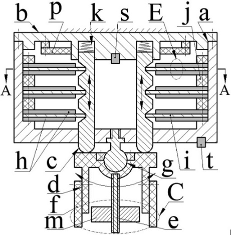
[0028] A self-powered bridge monitoring device, mainly including a casing a, a cover b, a push rod c, a coupler C, a ball stud g, a transducer E, a spring k, a circuit board p, a sensor one s and a sensor two t.

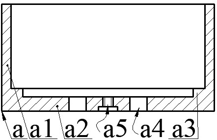
[0029] The casing a is composed of the casing wall a1 and the casing bottom a2. The casing bottom a2 is provided with a ring platform a3, a threaded hole a5 and a group of lower guide holes a4. The ring platform a3 is located on the casing wall a1 and the casing bottom a2. The lower guide holes a4 are through holes and are evenly distributed on the circumference with the center of the casing bottom a2 as the center, and the threaded holes a5 are located at the center of the casing bottom a2.

[0030] The barrel-shaped coupler C is hung on the bottom a2 of the casing through the ball pin g. The ball pin g is composed of the pin head g1 and the pin g2. The pin g2 is installed on the bottom a2 of the casing through the thread at its end. The pin cavity on the barrel to...


PUM


Abstract

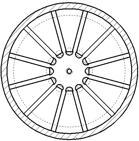
The invention discloses a self-powered bridge monitoring device, and belongs to the technical field of new energy and monitoring. The self-powered bridge monitoring device is characterized in that a machine cover is installed at the end of a machine shell wall, lower guide holes and upper guide holes are evenly distributed in a machine shell bottom and the machine cover respectively, a coupler is hung on the machine shell bottom through a ball head pin, the pin rod of the ball head pin is installed on the machine shell bottom, the coupler is installed on the pin head of the ball head pin, a plurality of groups of transducers are arranged on the machine shell bottom, a spacer ring is arranged between two axially adjacent groups of transducers, the groups of transducers are equal in number and are uniformly distributed along the circumferential direction, the transducer is formed by assembling a main vibrator and auxiliary vibrators on the upper side and the lower side of the main vibrator, the upper end and the lower end of a push rod are respectively arranged in the upper guide hole and the lower guide hole, the free end of the main vibrator is arranged in the shifting groove of the push rod, the upper end of the push rod presses a spring on the machine cover, the lower end of the push rod abuts against the coupler, the coupler swings in a reciprocating mode under the action of wind and forces the main vibrator and the auxiliary vibrators to be bent, deformed and alternately contacted and separated through the push rod, then mechanical energy is converted into electric energy, and the electric energy is supplied to a sensor and an information sending system after being converted and processed.

Description

technical field [0001] The invention belongs to the technical field of new energy, and in particular relates to a self-powered bridge monitoring device, which provides kinetic energy for a bridge monitoring system. Background technique [0002] Bridges have become an important part of today's road and rail networks. In order to ensure the normal and safe passage of cars and trains and to realize real-time monitoring of the bridge environment and surrounding environment, various instruments and equipment need to be installed on the bridge, so there must be corresponding power supply facilities on the bridge. At present, cables are commonly used for power supply. The laying of cables and subsequent maintenance are difficult and costly. The most critical thing is that the bridge monitoring system will not be able to operate normally when the power supply system fails. Therefore, people have developed various forms of self-powered bridge health monitoring systems, such as Chine...

Claims


Application Information

Patent Timeline
IPC IPC(8): H02N1/04H02N2/18F03D5/06
CPCH02N1/04H02N2/186F03D5/06Y02E10/70
Inventor 蒋永华夏倩雯毛燕飞姜焱鑫程光明吴鸣阚君武曾平
Owner ZHEJIANG NORMAL UNIVERSITY
Learn More