Industrial sewage treatment device

A technology for treating device and industrial sewage, applied in sludge treatment, water/sludge/sewage treatment, chemical instruments and methods, etc. To avoid problems such as the reduction of circulating performance, to avoid contact friction, improve self-cleaning ability, and ensure the effect of dehydration efficiency

Active Publication Date: 2022-04-08
宁夏环保集团有限责任公司
View PDF20 Cites 0 Cited by
  • Summary
  • Abstract
  • Description
  • Claims
  • Application Information

AI Technical Summary

Problems solved by technology

[0003]The traditional stacked screw sludge dewatering machine is mainly composed of a fixed ring, a moving ring, a gasket, a screw shaft and other components. The fixed ring and the moving ring are sleeved on Outside the screw shaft, the gasket is placed between the fixed ring and the moving ring, so that the fixed ring and the moving ring are assembled together to form a filtering gap, and the sewage flows out from the filtering gap. When working, the screw shaft rotates and the moving ring The relative movement with the fixed ring can remove the sludge in the filter gap, so as to achieve the purpose of automatic cleaning. However, when the spiral blade of the screw shaft drives the swimming ring to swim in the gap between the fixed rings, the swimming ring There will be contact friction with the spiral blade, which will easily cause wear of the swimming ring and the spiral blade, the swimming performance of the swimming ring will gradually decrease, and the self-cleaning function of the equipment will deteriorate, resulting in a gradual decrease in dehydration efficiency;

Method used


Image

  • Industrial sewage treatment device
  • Industrial sewage treatment device
  • Industrial sewage treatment device

Examples


Embodiment Construction

[0047] In order to enable those skilled in the art to better understand the technical solutions of the present invention, the present invention will be further described in detail below in conjunction with the accompanying drawings.

[0048] see figure 1 shown;

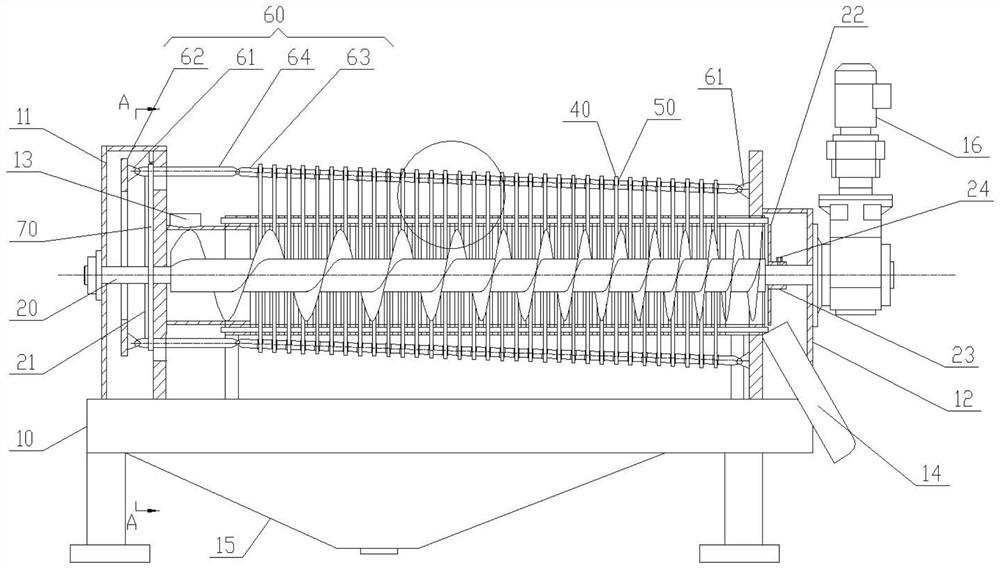
[0049] Invented an industrial sewage treatment device, including:

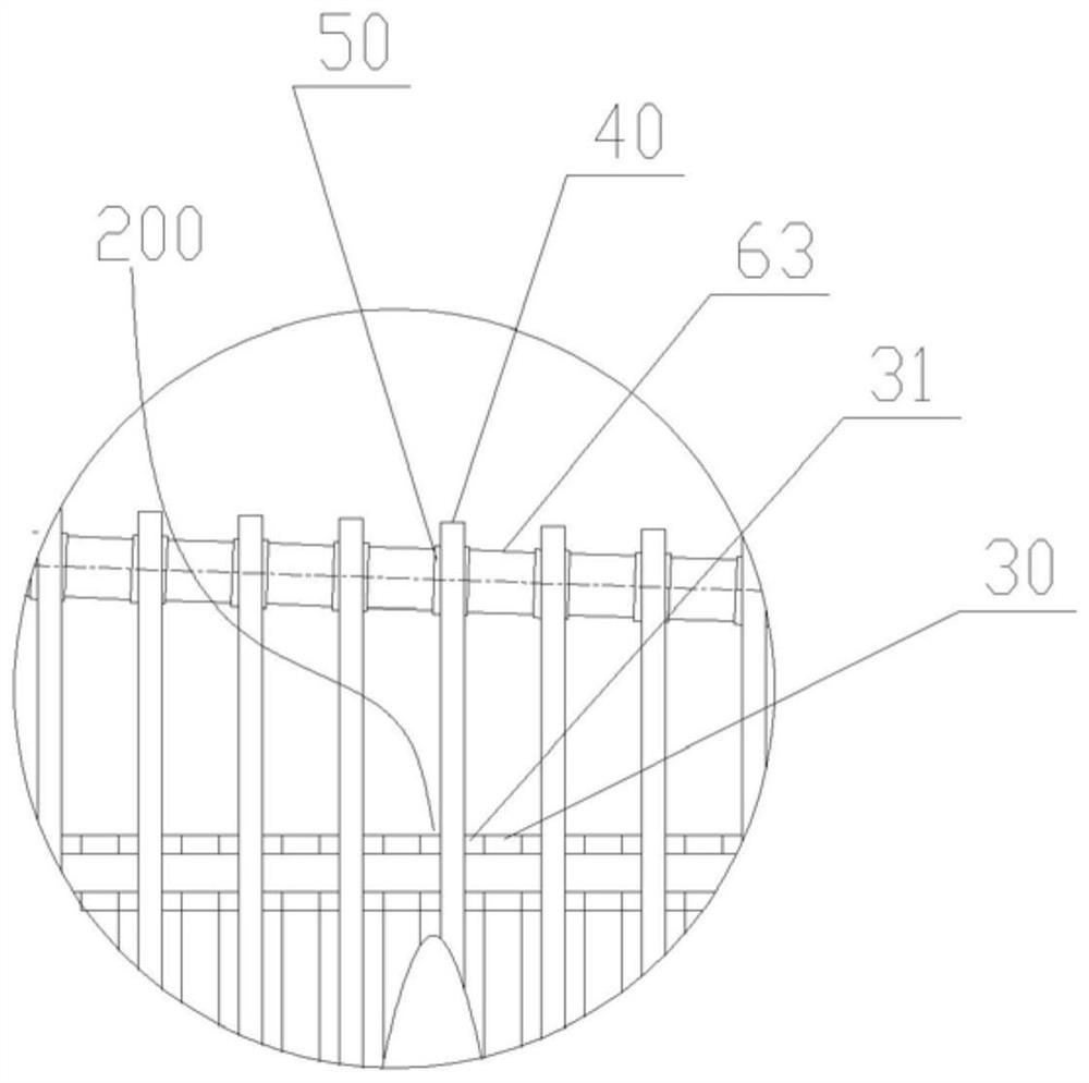
[0050] Set up the shell of the screw shaft 20 , set a number of fixed rings 30 and floating rings 40 that are arranged alternately on the screw shaft 20 in sequence, and a movement space 200 for forming the moving ring 40 is installed between two adjacent fixed rings 30 Gasket 31, one end of the housing is provided with a mud inlet 13, and the other end is provided with a mud outlet 14; wherein, it also includes a connecting rod structure 60 connecting several swimming rings 40 in sequence; and

[0051] A plurality of sheets 42, which are spliced ​​end to end in turn to form a circular structure of the floating ring 40, and the parting surface 100 f...


PUM


Abstract

The invention discloses an industrial sewage treatment device, and belongs to the technical field of sludge treatment equipment, the industrial sewage treatment device is provided with a shell for erecting a spiral shaft, a plurality of fixed rings and floating rings which sleeve the spiral shaft and are sequentially arranged in a staggered manner, and a gasket for forming a moving space of the floating rings is arranged between every two adjacent fixed rings; a sludge inlet is formed in one end of the shell, and a sludge outlet is formed in the other end of the shell; the connecting rod structure is sequentially connected with the floating rings; the floating ring comprises a plurality of connecting rod structures and a plurality of sheet bodies, the sheet bodies are sequentially spliced end to end to form the floating ring of a circular ring structure, a parting surface formed by contact of every two sheet bodies coincides with the circular shape of the floating ring, and every two adjacent sheet bodies are movably connected with the connecting rod structures through connecting parts. Abrasion is reduced, the service life is long, and the failure rate is low.

Description

technical field [0001] The invention relates to the technical field of sludge treatment equipment, in particular to an industrial sewage treatment device. Background technique [0002] Sludge is an inevitable product of sewage treatment in sewage treatment plants. Untreated sludge entering the environment will directly cause secondary pollution to water and the atmosphere, and pose a serious threat to the ecological environment and human activities. Sludge treatment can be divided into sewage Sludge dehydration process and sludge drying process; [0003] The traditional stacked screw sludge dewatering machine is mainly composed of a fixed ring, a moving ring, a gasket, a screw shaft and other components. The fixed ring and the moving ring are set outside the screw shaft, and the gasket is placed between the fixed ring and the moving ring. In this way, the fixed ring and the movable ring are assembled together to form a filter gap, and the sewage flows out from the filter ga...

Claims


Application Information

Patent Timeline
Patent Type & Authority Applications(China)
IPC IPC(8): C02F11/125
CPCY02W10/10
Inventor 孙鹏康金虎雷杰杨斐斐
Owner 宁夏环保集团有限责任公司
Why Eureka
Try Eureka