A welding rod automatic production system

A technology for automatic production and welding electrodes, applied in welding equipment, welding media, welding/cutting media/materials, etc., it can solve the problems of many environmental protection treatment points, increase personnel costs, and high maintenance costs, and reduce equipment investment and maintenance costs. The effect of reducing the configuration of production personnel and the overall structure of the equipment is simple

Active Publication Date: 2022-06-28
天津市金桥焊材科技有限公司 +1
View PDF10 Cites 0 Cited by
  • Summary
  • Abstract
  • Description
  • Claims
  • Application Information

AI Technical Summary

Problems solved by technology

[0003] 1. Low production efficiency: At present, after the wire is cut by the high-speed wire cutter, it needs to be stored in turnover, and the semi-finished welding core will be transferred in when the next process is needed, which wastes time in turnover;
[0004] 2. Many staffing: many production links, material turnover, material loading and unloading all require separate personnel to operate, thereby increasing personnel costs;
[0005] 3. Large investment in equipment and high maintenance cost: Due to the many process links involved in the production of existing welding rods, the cost of initial equipment investment and daily maintenance of equipment is very high, and the equipment occupies a large area. Generally, a process needs to be occupied a workshop space;
[0006] 4. Poor environmental protection, many processes, large land occupation, and many environmental protection management points

Method used


Image

  • A welding rod automatic production system
  • A welding rod automatic production system
  • A welding rod automatic production system

Examples


Embodiment Construction

[0042] The present invention will be further described below with reference to the accompanying drawings and specific embodiments.

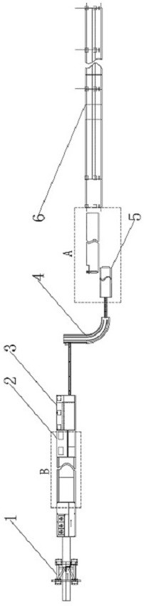
[0043] figure 1 A schematic structural diagram of an embodiment of the present invention is shown. This embodiment relates to an automatic welding rod production system for the production of welding rods. The welding rod automatic production system integrates the original segmented production as a whole to construct a The automatic production line can realize automatic production in all stages from the line entry stage to the electrode drying stage, reduce the investment of production equipment, avoid the temporary storage and turnover of materials between cutting and drawing, rotating and applying medicine, and reduce the configuration of production personnel. Reduce land space and improve production efficiency.

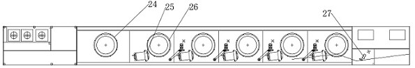
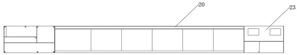
[0044] An automatic production system for welding electrodes, such as figure 1 , figure 2 and Image 6 As shown, it includes a w...


PUM


Abstract

The invention provides an automatic production system for welding rods, including a wire feeding device, a drawing device, a wire cutting device, a buffer device, a wire feeding device, a powder feeding device and a drying device, a wire feeding device, a drawing device, a wire cutting device, and a buffering device , wire feeding device, powder feeding device and drying device are arranged in sequence along the welding rod preparation direction to prepare welding rods; the wire feeding device is set to transport the coiled welding core in a single form, and the drawing device is set to It is used to draw the welding core, the wire cutting device is set to cut off the drawn welding core, and the buffer device is set to buffer and turn over the cut welding core during the conveying process, and wire feeding The device is set to convey the welding core when the welding core is covered by the coating, the powder feeding device is set to coat the welding core, and the drying device is set to dry the prepared welding rod . The invention has the beneficial effects of reducing production personnel allocation, reducing equipment investment and maintenance costs.

Description

technical field [0001] The invention belongs to the technical field of welding rod production, and in particular relates to an automatic welding rod production system. Background technique [0002] Welding technology plays a very important role in many infrastructure fields. As an important branch of welding materials, welding rod occupies a relatively high proportion in welding materials due to its fast welding speed and wide application range. At present, the domestic automatic production system of welding rod adopts the production process of single process and single workshop, and its technical shortcomings mainly include the following aspects: [0003] 1. Low production efficiency: At present, the wire rod needs to be stored in turnover after being cut by the high-speed wire cutter, and the semi-finished solder core will be transferred in when the next process requires it, and the turnover is a waste of time; [0004] 2. There are many personnel allocations: there are ...

Claims


Application Information

Patent Timeline
Patent Type & Authority Patents(China)
IPC IPC(8): B23K35/40B21C1/14B21C9/00
CPCB23K35/40B21C1/14B21C9/00
Inventor 侯云昌侯怀礼李欣郝建佟德勇
Owner 天津市金桥焊材科技有限公司
Why Eureka
Try Eureka