
Orthogonal mode coupler (OMT) testing tool

A technology of orthogonal mode coupler and test tooling, applied in the direction of measuring device, measuring device casing, instrument, etc., can solve the problem of increasing test time, etc., and achieve the effect of shortening test time, reducing test cost and improving efficiency

Pending Publication Date: 2022-02-18
安徽阖煦微波技术有限公司
View PDF0 Cites 0 Cited by
  • Summary
  • Abstract
  • Description
  • Claims
  • Application Information

AI Technical Summary

Problems solved by technology

[0002] In a microwave system, it is often necessary to divide one microwave power into several circuits in proportion. This is the problem of power distribution. The components that realize this function are called power distribution components or couplers, which mainly include directional couplers, power dividers and various components. A microwave branch device, a photoelectric coupler is an electric-optical-electric conversion device that transmits electrical signals through light as a medium. It consists of two parts: a light source and a light receiver. In the body, they are isolated from each other by a transparent insulator. The pin of the light source is the input end, and the pin of the light receiver is the output end. The common light source is a light-emitting diode, and the light receiver is a photodiode, phototransistor, etc. There are many types, such as photodiode type, phototransistor type, photoresistor type, photoelectric thyristor type, photoelectric Darlington type, integrated circuit type, etc., and the current industry testing orthogonal mode coupler (OMT) basically uses Port docking is carried out by locking the flange with four screws. This method is easy to scratch the DUT by the flange fastening screws during the test, and also greatly increases the test time.

Method used


Image

  • Orthogonal mode coupler (OMT) testing tool
  • Orthogonal mode coupler (OMT) testing tool
  • Orthogonal mode coupler (OMT) testing tool

Examples


Embodiment Construction

[0018] In order to make the above objects, features and advantages of the present invention more comprehensible, specific implementations of the present invention will be described in detail below in conjunction with the accompanying drawings. In the following description, numerous specific details are set forth in order to provide a thorough understanding of the present invention. However, the present invention can be implemented in many other ways different from those described here, and those skilled in the art can make similar improvements without departing from the connotation of the present invention, so the present invention is not limited by the specific embodiments disclosed below.

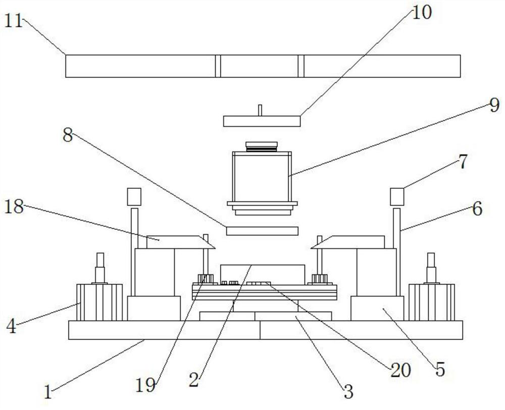
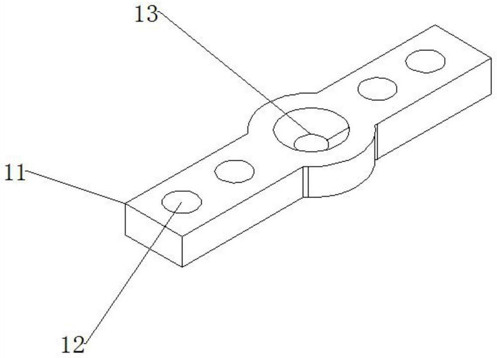
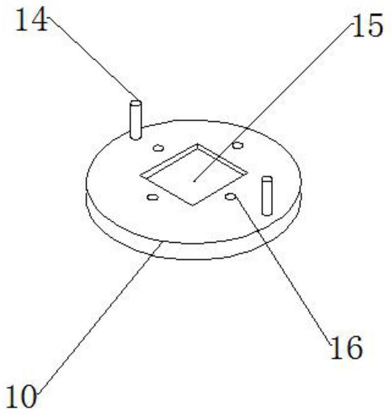
[0019] like Figure 1-5 As shown, the present invention provides a kind of orthogonal mode coupler (OMT) test fixture, a kind of orthogonal mode coupler (OMT) test fixture, comprises upper module and lower module, and described upper module includes upper mold core 9 , guide ring 8, nine...


PUM


Abstract

The invention relates to the technical field of microwave device testing devices, in particular to an orthogonal mode coupler (OMT) testing tool. The testing tool comprises an upper module and a lower module, the upper module comprises an upper mold core, a guide ring, a 90 DEG rotation stop block, an upper mold pull rod and two linear bearings, four second fixing holes are symmetrically formed in the center of the guide ring, the guide ring penetrates through the corresponding second fixing holes through bolts to be fixedly connected with the bottom of the upper die core, a square hole is formed in the center of the 90 DEG rotation stop block, the 90 DEG rotation stop block is slidably connected with the upper die core through the square hole, and four first fixing holes are symmetrically formed in the center of the 90 DEG rotation stop block. When the waveguide transmission port is butted in the S parameter test, screw locking is not needed, the damage probability of the DUT caused by screw locking is avoided, meanwhile, the test time is greatly shortened, the efficiency is improved, and the purpose of reducing the test cost is achieved.

Description

technical field [0001] The invention relates to the technical field of microwave device testing devices, in particular to an orthogonal mode coupler (OMT) testing tool. Background technique [0002] In a microwave system, it is often necessary to divide one microwave power into several circuits in proportion. This is the problem of power distribution. The components that realize this function are called power distribution components or couplers, which mainly include directional couplers, power dividers and various components. A microwave branch device, a photoelectric coupler is an electric-optical-electric conversion device that transmits electrical signals through light as a medium. It consists of two parts: a light source and a light receiver. In the body, they are isolated from each other by a transparent insulator. The pin of the light source is the input end, and the pin of the light receiver is the output end. The common light source is a light-emitting diode, and the...

Claims


Application Information

Patent Timeline
Patent Type & Authority Applications(China)
IPC IPC(8): G01R1/04G01R31/00
CPCG01R1/0408G01R31/00
Inventor 汪峰顾春健杨宋兵李慧勇
Owner 安徽阖煦微波技术有限公司
Learn More