
Heat dissipation device

A technology of heat dissipation device and radiator, applied in lighting and heating equipment, instruments, electrical digital data processing and other directions, can solve the problems of insufficient energy consumption of the pump and low heat dissipation efficiency, to improve the heat dissipation demand, improve the heat dissipation efficiency, and realize the CPU The effect of cooling efficiency

Pending Publication Date: 2022-02-18
XI AN JIAOTONG UNIV
View PDF0 Cites 0 Cited by
  • Summary
  • Abstract
  • Description
  • Claims
  • Application Information

AI Technical Summary

Problems solved by technology

[0005] Based on the problems of low heat dissipation efficiency of existing heat sinks and insufficient energy consumption of pumps, this application provides a heat sink

Method used


Image

  • Heat dissipation device
  • Heat dissipation device
  • Heat dissipation device

Examples


Embodiment

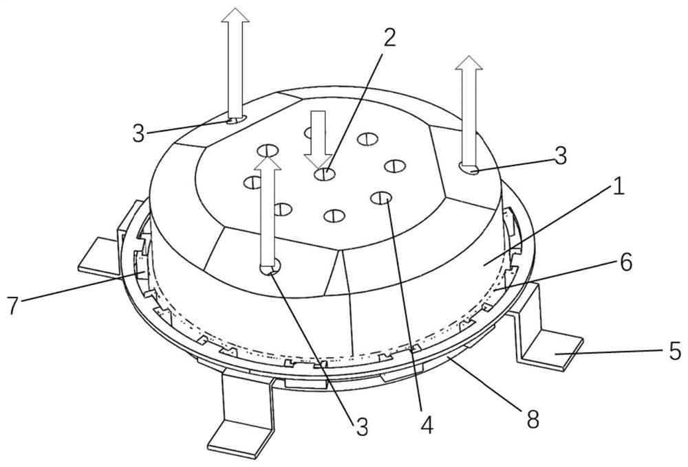
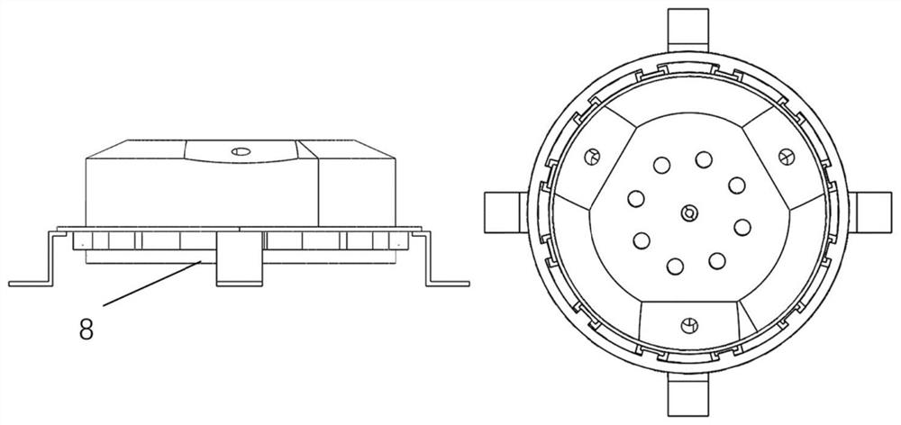
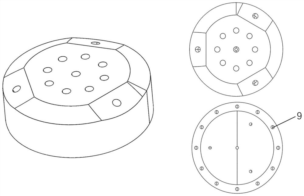
[0054] The present application provides a three-taper microchannel evaporator using nanofluids, including a refrigerant manifold block 1, an assembly frame 5, a silicone gasket 6, an assembly ring 7, a microchannel radiator 8 and a copper sheet. The bottom is matched with each other, and the middle is connected by bolts to form a whole; the refrigerant manifold block 1 includes a refrigerant inlet 2, three refrigerant outlets 3, and 8 grooves 4 for placing magnets for attracting nanofluids. , the outlet of the three refrigerant steam risers is 120 degrees from each other, the refrigerant inlet 2 is the liquid nano-fluid flow channel flowing out from the condenser; the assembly frame 5, the silicone gasket 6, the assembly ring and the microchannel The radiator and its surrounding copper sheets 8 cooperate to form the entire evaporator; the micro-channel radiator channel and its surrounding copper sheets 8 are structured as a section of wave-shaped structure connected to a sectio...


PUM


Abstract

The invention belongs to the technical field of heat dissipation, and particularly relates to a heat dissipation device. An existing heat dissipation device is low in heat dissipation efficiency, and energy consumed by a pump is insufficient. The invention provides a heat dissipation device which comprises a condenser, a refrigerant manifold check block and an evaporator which are connected in sequence, the refrigerant manifold check block is provided with a refrigerant inlet and a refrigerant outlet, and the evaporator comprises a micro-channel radiator. The condenser, the refrigerant inlet and the micro-channel radiator form a first refrigerant flowing channel, the condenser, the refrigerant outlet and the micro-channel radiator form a second refrigerant flowing channel, the refrigerant inlet is provided with a first filter screen, and the refrigerant outlet is provided with a second filter screen. And the heat dissipation efficiency of the CPU is improved.

Description

technical field [0001] The present application belongs to the technical field of heat dissipation, and in particular relates to a heat dissipation device. Background technique [0002] CPU is the abbreviation of central processing unit, which is one of the main devices of electronic computers and the core accessories in computers. Its main function is to interpret computer instructions and process data in computer software. The CPU is the core component in a computer responsible for reading instructions, decoding them, and executing them. In the computer architecture, the CPU is the core hardware unit that regulates all hardware resources of the computer and performs general-purpose operations. The CPU is the computing and control core of a computer, and the final execution unit for information processing and program operation. The operation of all software layers in the computer system will eventually map the operation of the micro CPU through the instruction set. Over ...

Claims


Application Information

Patent Timeline
IPC IPC(8): G06F1/20F25B39/00F25B41/40F25B43/00
CPCG06F1/20F25B39/00F25B41/40F25B43/003Y02D10/00
Inventor 杨松杨梦莹张翌晨蔡彧青张平侯予
Owner XI AN JIAOTONG UNIV
Learn More