Composite material electric pole of braided structure

A composite material and pole technology, which is used in woven fabrics, textiles, papermaking, construction, etc., can solve the problems of inconvenient installation and transportation, long service life, high mechanical strength of ferroelectric poles, etc. Insulation and anti-corrosion effect, the effect of easy line connection

Pending Publication Date: 2022-02-22
山东广域科技有限责任公司
View PDF6 Cites 0 Cited by
  • Summary
  • Abstract
  • Description
  • Claims
  • Application Information

AI Technical Summary

Problems solved by technology

[0002] Electric poles are widely used in electric power, communication and signal poles and other projects. Our common electric poles include wooden electric poles, concrete electric poles and iron electric poles. Among them, wooden electric poles have the advantages of light weight and insulation. The disadvantage is that the structural strength is low, not fireproof, and not corrosion-resistant; the concrete pole has high structural strength and can bear a large weight, but the disadvantage is that the volume and weight are large and inconvenient for installation and transportation; the iron pole has high mechanical strength and is easy to use. Advantages such as long service life, the disadvantage is that it is not insulated, and has weak resistance to the atmosphere, water, general concentrations of acids, alkalis, salts, and various oils and solvents

Method used


Image

  • Composite material electric pole of braided structure
  • Composite material electric pole of braided structure
  • Composite material electric pole of braided structure

Examples


Embodiment 1

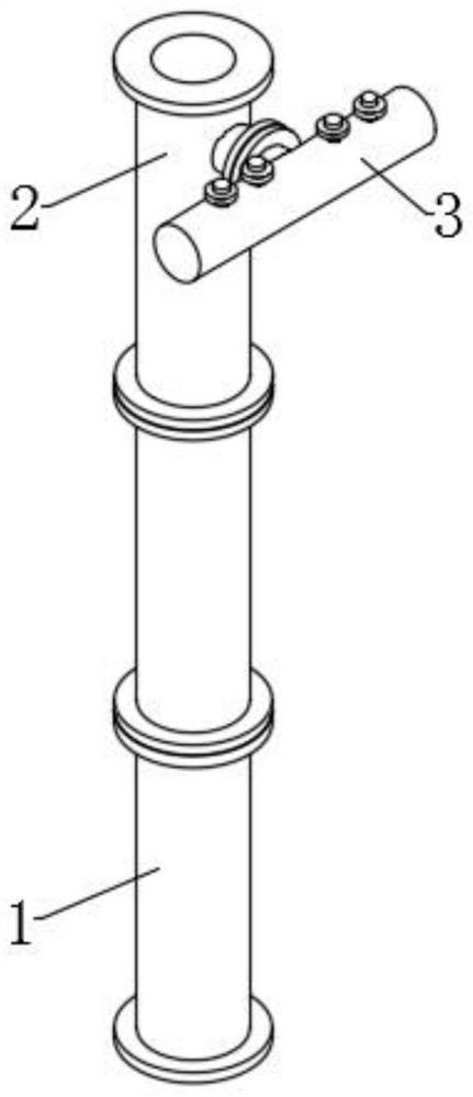
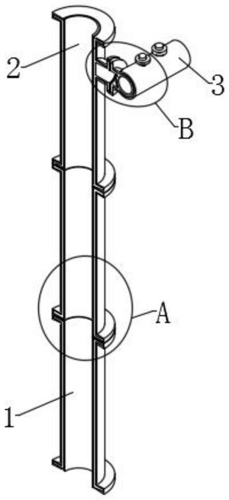
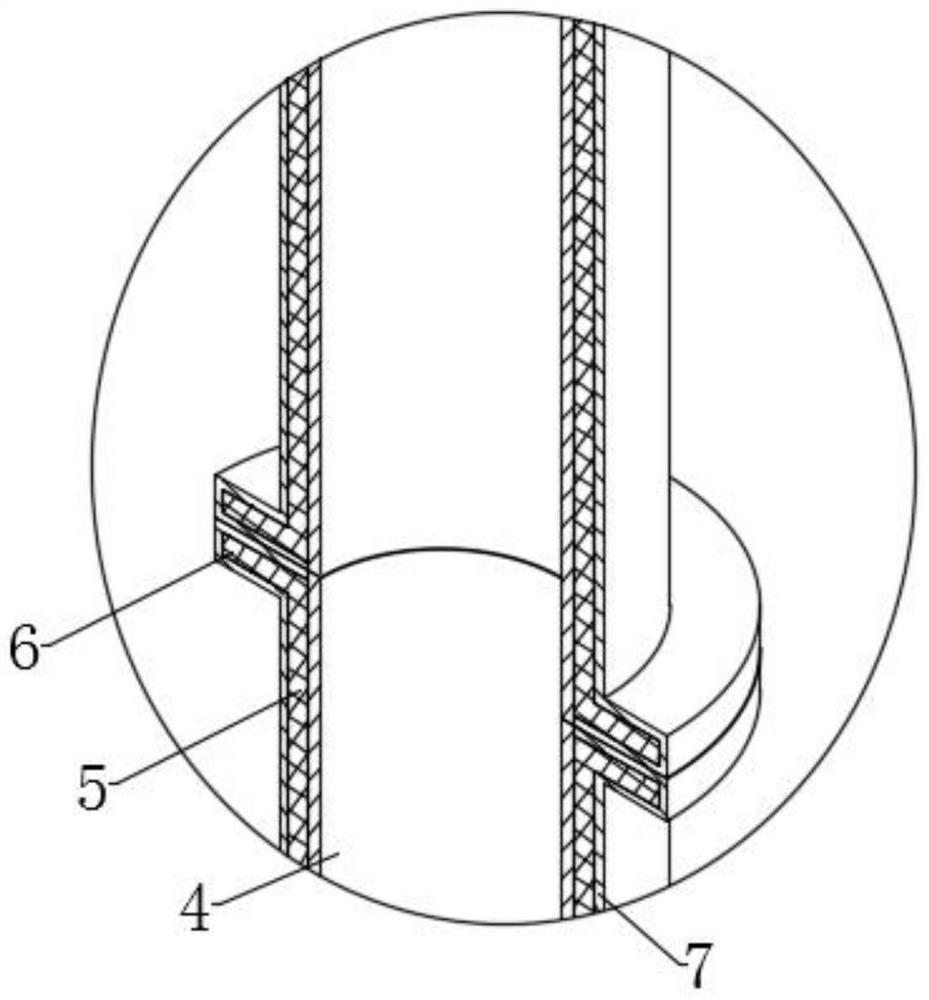
[0026] Embodiment 1: as Figure 1 to Figure 4 As shown, the present invention provides a composite pole with braided structure, including a shaft 1, a rod end 2 and a cross arm 3, the shaft 1 includes a first profile 5, and the rod end 2 and the cross arm 3 include a second profile 8. The peripheral outer wall of the second profile 8 is integrally formed with a second flange ring 9, and the two ends of the first profile 5 and the two ends of the second profile 8 at the rod end 2 are integrally formed with a first flange ring 6. The outer wall of the second profile 8 at the cross arm 3 is integrally formed with a plurality of terminals 10, the inner cavities of the first profile 5 and the second profile 8 are provided with an inner braiding layer 4, the first profile 5 and the second profile 8 The outer walls of each are provided with an outer braided layer 7.

[0027] Further, the first flange ring 6 , the second flange ring 9 and the terminal 10 are all covered in the outer ...

Embodiment 2

[0034] Embodiment 2: as Figure 1 to Figure 4 As shown, the present invention provides a composite pole with braided structure, including a shaft 1, a rod end 2 and a cross arm 3, the shaft 1 includes a first profile 5, and the rod end 2 and the cross arm 3 include a second profile 8. The peripheral outer wall of the second profile 8 is integrally formed with a second flange ring 9, and the two ends of the first profile 5 and the two ends of the second profile 8 at the rod end 2 are integrally formed with a first flange ring 6. The outer wall of the second profile 8 at the cross arm 3 is integrally formed with a plurality of terminals 10, the inner cavities of the first profile 5 and the second profile 8 are provided with an inner braiding layer 4, the first profile 5 and the second profile 8 The outer walls of each are provided with an outer braided layer 7.

[0035] Further, the first flange ring 6 , the second flange ring 9 and the terminal 10 are all covered in the outer ...

Embodiment 3

[0042] Embodiment 3: as Figure 1 to Figure 4 As shown, the present invention provides a composite pole with braided structure, including a shaft 1, a rod end 2 and a cross arm 3, the shaft 1 includes a first profile 5, and the rod end 2 and the cross arm 3 include a second profile 8. The peripheral outer wall of the second profile 8 is integrally formed with a second flange ring 9, and the two ends of the first profile 5 and the two ends of the second profile 8 at the rod end 2 are integrally formed with a first flange ring 6. The outer wall of the second profile 8 at the cross arm 3 is integrally formed with a plurality of terminals 10, the inner cavities of the first profile 5 and the second profile 8 are provided with an inner braiding layer 4, the first profile 5 and the second profile 8 The outer walls of each are provided with an outer braided layer 7.

[0043] Further, the first flange ring 6 , the second flange ring 9 and the terminal 10 are all covered in the outer ...


PUM

PropertyMeasurementUnit
thicknessaaaaaaaaaa
thicknessaaaaaaaaaa

Abstract

The invention discloses a composite material electric pole of a braided structure and belongs to the technical field of electric poles. The composite material electric pole comprises a pole body, a pole end and a cross arm, wherein the pole body comprises a first profile, the pole end and the cross arm comprise a second profile, and a second flange ring is integrally formed on a circumferential outer wall of the second profile; first flange rings are integrally formed at two ends of the first section bar and two ends of the second section bar at a rod end, a plurality of terminals are integrally formed on an outer wall of the second section bar at the cross arm, inner braid layers are arranged in inner cavities of the first section bar and the second section bar, and outer braid layers are arranged on outer walls of the first section bar and the second section bar. The electric pole has high strength, corrosion resistance and aging resistance through solidification of reinforced thermosetting resin of the inner braid layer and the outer braid layer, the pole body, the pole end and the cross arm are small in size and convenient to transport, during installation, the first flange rings between the pole body and the pole end are bolted through bolts, and the second flange rings between the pole end and the cross arm are bolted through bolts; and assembling and using of the electric pole are achieved.

Description

technical field [0001] The invention relates to the technical field of electric poles, in particular to a composite material electric pole with a braided structure. Background technique [0002] Electric poles are widely used in electric power, communication and signal poles and other projects. Our common electric poles include wooden electric poles, concrete electric poles and iron electric poles. Among them, wooden electric poles have the advantages of light weight and insulation. The disadvantage is that the structural strength is low, not fireproof, and not corrosion-resistant; the concrete pole has high structural strength and can bear a large weight, but the disadvantage is that the volume and weight are large and inconvenient for installation and transportation; the iron pole has high mechanical strength and is easy to use. It has the advantages of long service life, etc., but the disadvantage is that it is not insulated, and has weak resistance to the atmosphere, wat...

Claims


Application Information

Patent Timeline
Patent Type & Authority Applications(China)
IPC IPC(8): E04H12/02E04H12/24C08K7/26C08K3/26C08K3/04C08L63/10D04C1/02D04C1/06
CPCE04H12/02E04H12/24C08K7/26C08K3/26C08K3/042D04C1/02D04C1/06C08K2003/265C08K2201/011C08L63/10
Inventor 闵锐戴吉勇孙建瑞孟宾郭锐平金明侯梦琪苏彬王坤胡乃欣
Owner 山东广域科技有限责任公司
Why Eureka
Try Eureka