Eureka AIR delivers breakthrough ideas for toughest innovation challenges, trusted by R&D personnel around the world.

Polarization type LED light-emitting device and manufacturing method thereof

A technology for a light-emitting device and a manufacturing method, which is applied to electrical components, circuits, semiconductor devices, etc., can solve problems such as affecting user experience, prone to failure, affecting heat dissipation, etc., and achieves increasing 3D polarized display mode, reducing power consumption, and reducing thickness. Effect

Pending Publication Date: 2022-02-22
ZHENGZHOU CANBEST PHOTOELECTRIC TECH CO LTD
View PDF4 Cites 0 Cited by
  • Summary
  • Abstract
  • Description
  • Claims
  • Application Information

AI Technical Summary

Problems solved by technology

[0004] The patent number is 201910496353.1, and the announcement number is CN110098179A. The patent discloses a "SMD LED lamp bead emitting polarized light and its batch production method". The invention discloses the structure and batch production method of the SMD LED lamp bead. The polarizing film Paste each LED one by one in actual application, and found that the range of polarization display, brightness and other factors will directly affect the user experience, especially in the use of theaters, the visual experience is obvious, and the additional polarizing film structure is harmful to the user experience. The display range and brightness of the LED have a weakening effect. In order to increase the brightness, the power of the lamp bead may be increased, so that the heat generation of the display screen will increase, which will affect the heat dissipation of its use, and it is prone to failure.

Method used


Image

  • Polarization type LED light-emitting device and manufacturing method thereof
  • Polarization type LED light-emitting device and manufacturing method thereof
  • Polarization type LED light-emitting device and manufacturing method thereof

Examples


Embodiment 1

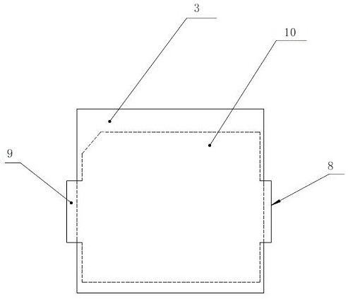
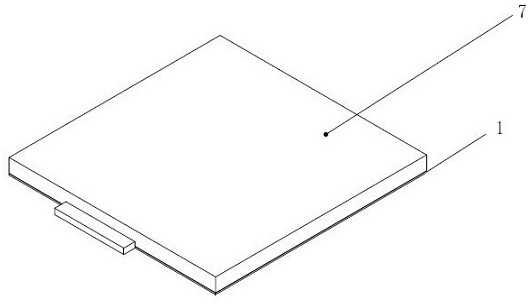
[0033] Embodiment one: see figure 1 , 2 To 6, technical scheme of the present invention is:

[0034] A polarized LED light-emitting device, comprising a single light-emitting chip and a polarized light-transmitting layer. The light-emitting chip is located at the bottom of the LED light-emitting device, and the polarized light-transmitting layer is located directly above it. A light-transmitting glue is arranged between the chip and the polarized light-transmitting layer, and a light-shielding component is arranged on the periphery of the light-emitting chip.

[0035] The polarized light-transmitting layer is a glass polarizer.

[0036] The glass polarizer adopts a multi-layer film structure, and oblong nanoparticles are embedded in one layer, and are sandwiched between two adjacent sheets.

[0037] The glass polarizer adopts two different crystal materials, which are glued together through a wedge-shaped structure, one is in the lower layer, and the other is in the upper l...

Embodiment 2

[0052] Embodiment two: with reference to attached image 3 , is generally the same as Embodiment 1, the difference is that the polarized light-transmitting layer adopts a multi-layer film structure, wherein two layers are glass slides, and oblong nanoparticles are embedded in the middle of the two layers, so that the glass slides It has a linear grid effect and can selectively transmit the light generated by the light-emitting chip.

[0053] Step 1: Use adhesive to fix the LED chip on the circuit board or bracket, and use wires to connect the positive and negative poles of the chip to the substrate;

[0054] Step 2﹑preheating the semi-finished product formed in step 1;

[0055] Step 3: Use a glue dispenser to dispense glue in step 3 with A glue, the thickness is enough to cover the LED power generation chip;

[0056] Step 4. Bake the semi-finished product in step 3 to cure the light-transmitting glue filled in each LED lamp bead bracket;

[0057] Step 5: Paste the prepared ...


PUM


Abstract

The invention relates to an LED display device, and especially relates to a polarization type LED light-emitting device. The device comprises a single light-emitting wafer and a polarization type light-transmitting layer, the light-emitting wafer is located on the bottom layer of the LED light-emitting device and comprises R, G and B three-color display, the polarization type light-transmitting layer is located over the light-emitting wafer, a protective film is arranged on the outer layer of the polarization type light-transmitting layer, light-transmitting glue is filled between the light-emitting wafer and the polarization light-transmitting layer, and a shading part is arranged on the periphery of the light-emitting wafer. According to the polarization type LED light-emitting device, the later-stage manufacturing difficulty is reduced, the thickness is reduced, the power consumption is reduced, the brightness is improved, and the effective visual range is widened; and an existing 3D polarization display mode is added, and later maintenance is facilitated.

Description

technical field [0001] The invention relates to an LED display device, in particular to a polarized LED light emitting device. Background technique [0002] The existing LED display screens are mainly divided into flat display and 3D stereoscopic display. The early LED display screens mainly use single-color or multi-color LED light-emitting lamp beads, and the display content information is realized through the control circuit on the back, and the color is single; with the technology With the advancement of technology and the improvement of production technology, LED color display technology has been applied, and there are many applications such as outdoor curtain walls and advertising displays; people's application of LED display technology has gradually expanded to media applications, and consumers feel the most obvious three-dimensional LED display in close contact. The display screen uses polarized LED display technology. The polarizing film made of the traditional pola...

Claims


Application Information

Patent Timeline
IPC IPC(8): H01L33/50H01L33/58
CPCH01L33/58H01L33/507H01L2933/0041
Inventor 不公告发明人
Owner ZHENGZHOU CANBEST PHOTOELECTRIC TECH CO LTD
Why Eureka
Eureka Blog
Learn More