
Movable spot beam antenna suitable for Mars surface landing and patrol detection

A patrol detection and spot beam technology, which is applied to antennas, antennas, folded antennas and other directions suitable for movable objects, can solve problems such as unfavorable electrical performance indicators of the antenna system, increasing the resistance distance of the mechanism components, and hindering the normal rotation of the mechanism, etc. To achieve the effect of reducing the increase of the additional envelope, reducing the drag distance, and avoiding the difficulty of pointing adjustment

Pending Publication Date: 2022-02-22
BEIJING INST OF SPACECRAFT SYST ENG
View PDF0 Cites 0 Cited by
  • Summary
  • Abstract
  • Description
  • Claims
  • Application Information

AI Technical Summary

Problems solved by technology

[0004] ① The thermal mismatch of the materials and structures in the two links of the radio frequency system and the antenna assembly-support structure-mechanism assembly in parallel will easily cause additional torque to the rotary joints in the radio frequency link, thereby increasing the resistance distance of the mechanism assembly and hindering the Mechanism rotates normally
In the X-band used for Mars rover communication, the waveguide has a large aperture size, but limited by the envelope requirements of the Mars rover, the antenna component itself has a small size, so the length of the waveguide used to adjust the direction of the main mode of waveguide transmission is limited. When the combination of curved waveguides realizes direction adjustment, it will bring about large antenna rotation interference and cause obstacles to the installation of antenna pressing devices, etc., while shorter twisted waveguides have disadvantages such as large differential loss, which is not conducive to realizing the electrical performance indicators of the antenna system Require
[0006] ③It is difficult for the Mars rover to accept the additional envelope increase brought by the compressed state of the antenna system to the Mars rover
When the antenna is installed on the top of the Mars rover, it needs to be installed on the solar panel and other loads in a compressed state, plus its own height envelope. This method not only has a great impact on the solar panel and other loads, Increase the coupling between devices, and greatly exceed the height direction envelope of the Mars rover; and when installing on the side wall, there are two specific methods. One is to set the installation surface to a relatively concave side wall position on the Mars rover. At this time, it is convenient It meets the additional envelope requirements, but the corresponding protruding position on the Mars rover causes limited deployment, which cannot meet the needs of the post-deployment work; the second is that the installation surface can be set on the side wall of the Mars rover roof that forms the protruding position. When the antenna is installed, the envelope requirement will be unacceptable to the Mars rover

Method used


Image

  • Movable spot beam antenna suitable for Mars surface landing and patrol detection
  • Movable spot beam antenna suitable for Mars surface landing and patrol detection
  • Movable spot beam antenna suitable for Mars surface landing and patrol detection

Examples


Embodiment Construction

[0030] The present invention will be described in detail below with reference to the accompanying drawings and examples.

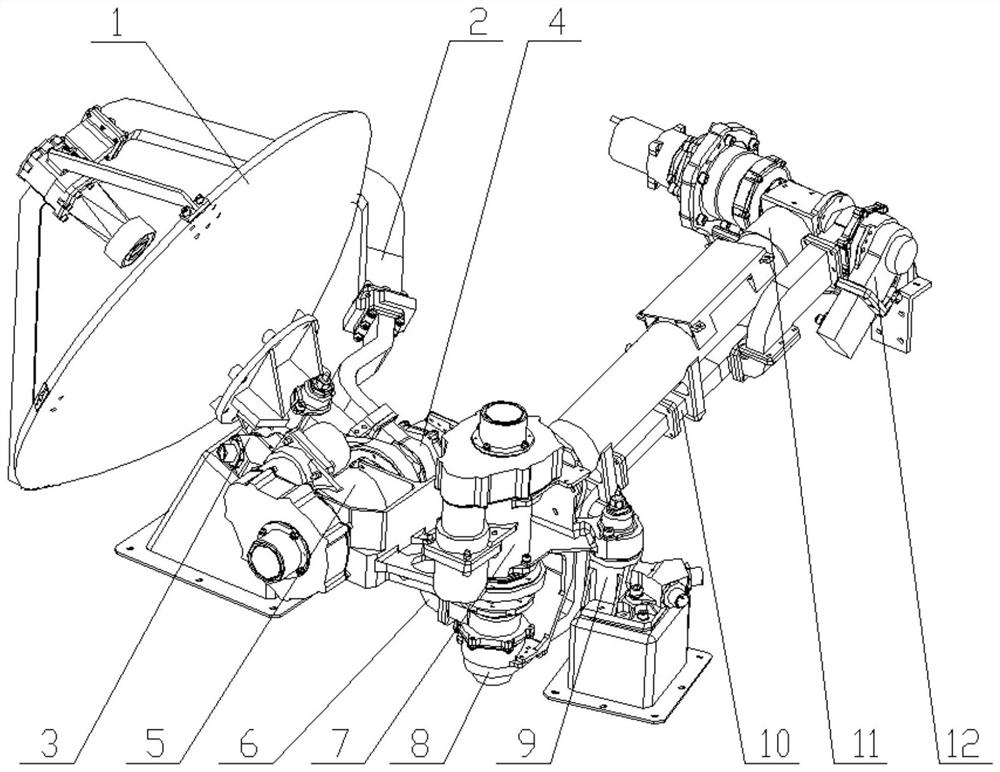
[0031] The present invention provides a movable spot beam antenna suitable for Mars surface landing and patrol detection, including an antenna assembly 1, a waveguide assembly C2, a pressing device B3, a rotary joint C4, a pointing drive shaft B5, and a waveguide assembly B 6. Pointing drive shaft A 7, rotary joint B 8, compression device A 9, waveguide assembly A 10, deployment device 11, rotary joint A 12, such as figure 1 shown.

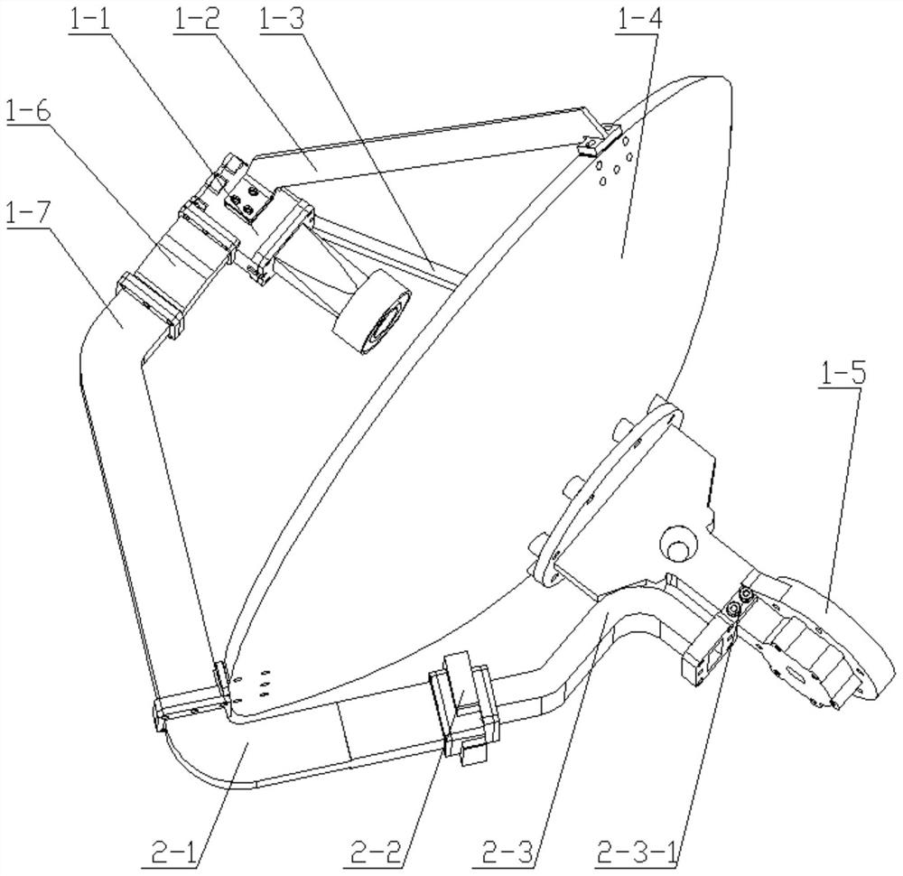
[0032] Antenna component 1 is the functional subject of the antenna system, such as figure 2 As shown, the antenna assembly 1 is a reflector antenna assembly, including feed 1-1, feed support A 1-2, feed support B1-3, reflector 1-4, antenna support 1-5, waveguide D1- 6 and waveguide E1-7, wherein waveguide D1-6 and waveguide E1-7 adopt the dedicated waveguide aperture of feed source 1-1, waveguide D1-6 and waveguide E1-7 ar...


PUM


Abstract

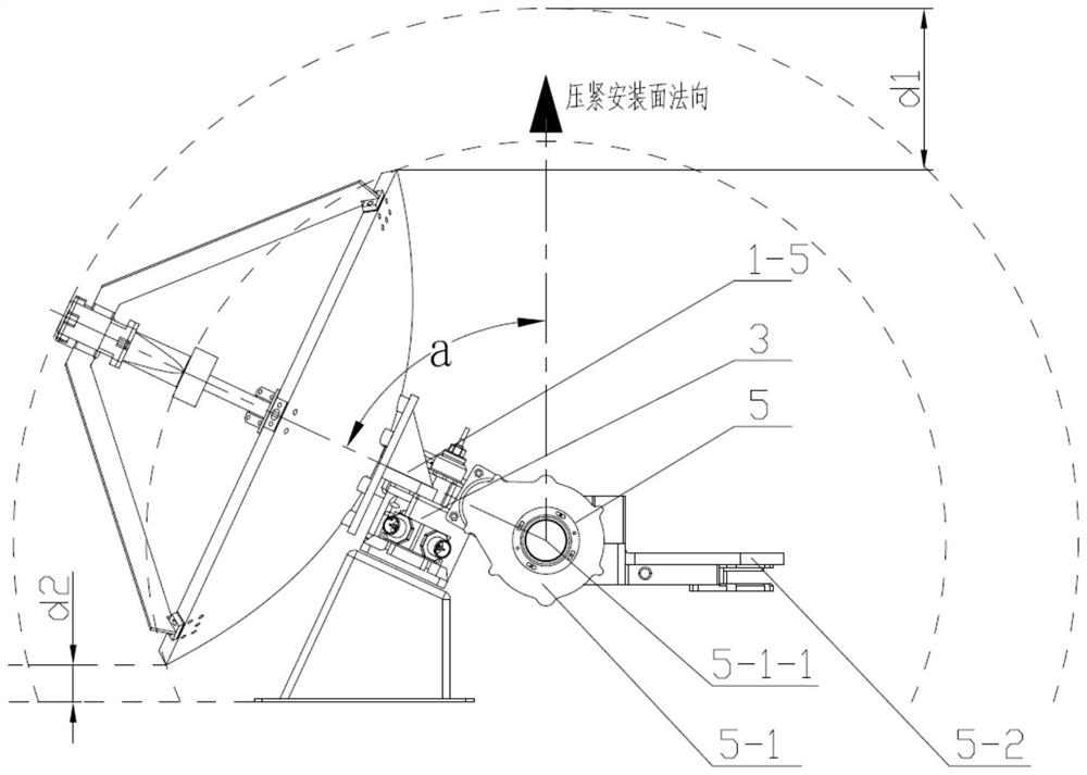
The invention discloses a high-gain movable spot beam antenna suitable for Mars landing and patrol detection. According to the invention, a feed source is supported by a waveguide D-waveguide E and other two supporting members in a three-point manner and is suspended in the center of a reflecting surface, so that the influence of the supporting structure on the antenna performance is effectively reduced; and meanwhile, the waveguide calibers of the waveguide D, the waveguide E and the feed source are changed, so that the miniaturization of the feed source is effectively realized, and the shielding influence of the feed source is reduced; meanwhile, a non-compact antenna assembly pressing structure is adopted, and a pressing mounting surface with a height difference and a mounting surface provided by an unfolding supporting structure are adopted, so that the working requirement after the antenna is unfolded is met, and meanwhile, the maximum additional envelope after the antenna is installed can reach the maximum height size of an unfolding driving shaft assembly part to the minimum, so the additional envelope is greatly reduced, and the application envelope requirement of the Mars rover is met.

Description

technical field [0001] The invention relates to the technical field of microwave antennas, and relates to a high-gain movable spot beam antenna suitable for Mars landing patrol detection. The antenna system can be applied to our country's Mars exploration mission, and can also be applied to other deep space exploration landing patrols with similar requirements. Background technique [0002] In the Mars exploration project, the Mars rover that lands on the surface of Mars and conducts landing and patrolling on the surface of Mars needs to be equipped with a pair of high-gain movable spot beam antennas. Satellites for high-speed communications. [0003] In order to realize communication with the Earth and artificial Mars satellites, the high-gain movable spot beam antenna for the Mars rover needs to combine the antenna assembly with the deployment mechanism, pointing drive mechanism, compression and release mechanism, and related support structures and radio frequency transmi...

Claims


Application Information

Patent Timeline
Patent Type & Authority Applications(China)
IPC IPC(8): H01Q1/22H01Q1/27H01Q1/50H01Q3/02H01Q15/16H01Q1/08
CPCH01Q1/22H01Q1/50H01Q3/02H01Q1/27H01Q15/16H01Q1/08
Inventor 段江年刘志佳孙大媛于国庆许怡贤鲁帆侯沁芳周晓东于春宇曾惠忠张旺军张婷庄建楼陈腾博赵香妮范占春陈百超
Owner BEIJING INST OF SPACECRAFT SYST ENG
Learn More