Electric compressor, inverter manufacturing apparatus and inverter manufacturing method

A technology for electric compressors and manufacturing devices, which is applied in the direction of machines/engines, liquid fuel engines, output power conversion devices, etc. It can solve problems such as poor welding, damage to inverters, damage to switching elements, etc., to prevent damage, The effect of preventing poor welding

Pending Publication Date: 2022-02-22
HANON SYST
View PDF5 Cites 0 Cited by
  • Summary
  • Abstract
  • Description
  • Claims
  • Application Information

AI Technical Summary

Problems solved by technology

[0006] However, in the conventional electric compressor, inverter manufacturing apparatus, and inverter manufacturing method as described above, since a plurality of elements cannot be fixed before the welding process, they may be detached from predetermined positions, thereby Problems leading to poor welding
[0007] In addition, there may be a problem that switching elements, which are easily affected by heat, may be damaged by heat during soldering.
[0008] In addition, there may be a problem that the inverter may be damaged due to the heat generated by the switching elements when checking the normal operation of multiple elements and switching elements after welding.
[0009] In addition, the inverter may be installed due to the difference in stress applied to the components and switching elements during welding and the stress applied to the components and switching elements after the inverter is mounted on the electric compressor. After arriving at the electric compressor, the welding parts of multiple components were damaged.

Method used


Image

  • Electric compressor, inverter manufacturing apparatus and inverter manufacturing method
  • Electric compressor, inverter manufacturing apparatus and inverter manufacturing method
  • Electric compressor, inverter manufacturing apparatus and inverter manufacturing method

Examples


Embodiment Construction

[0051] Next, a detailed description will be described in detail with reference to the drawings of the electric compressor, inverter manufacturing apparatus, and inverter manufacturing method.

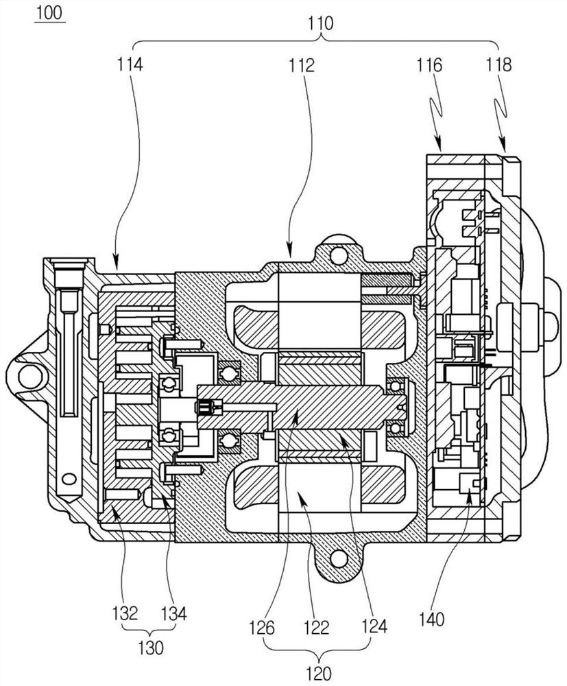
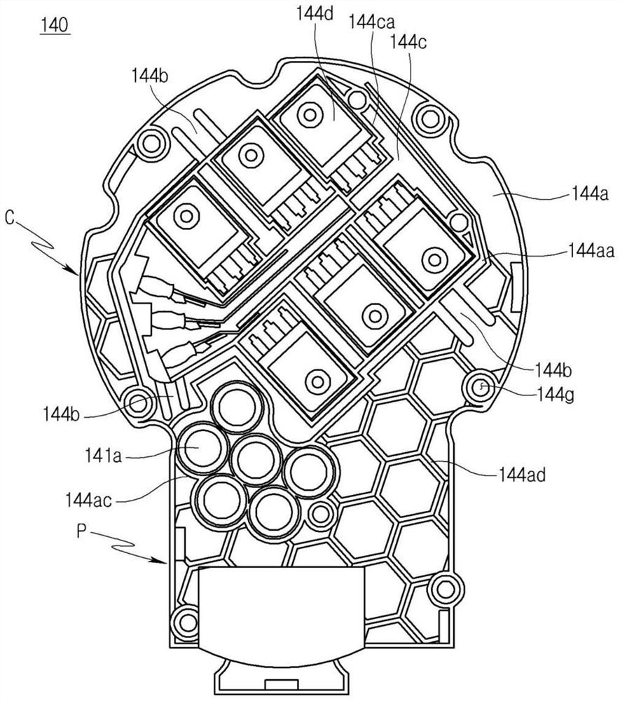
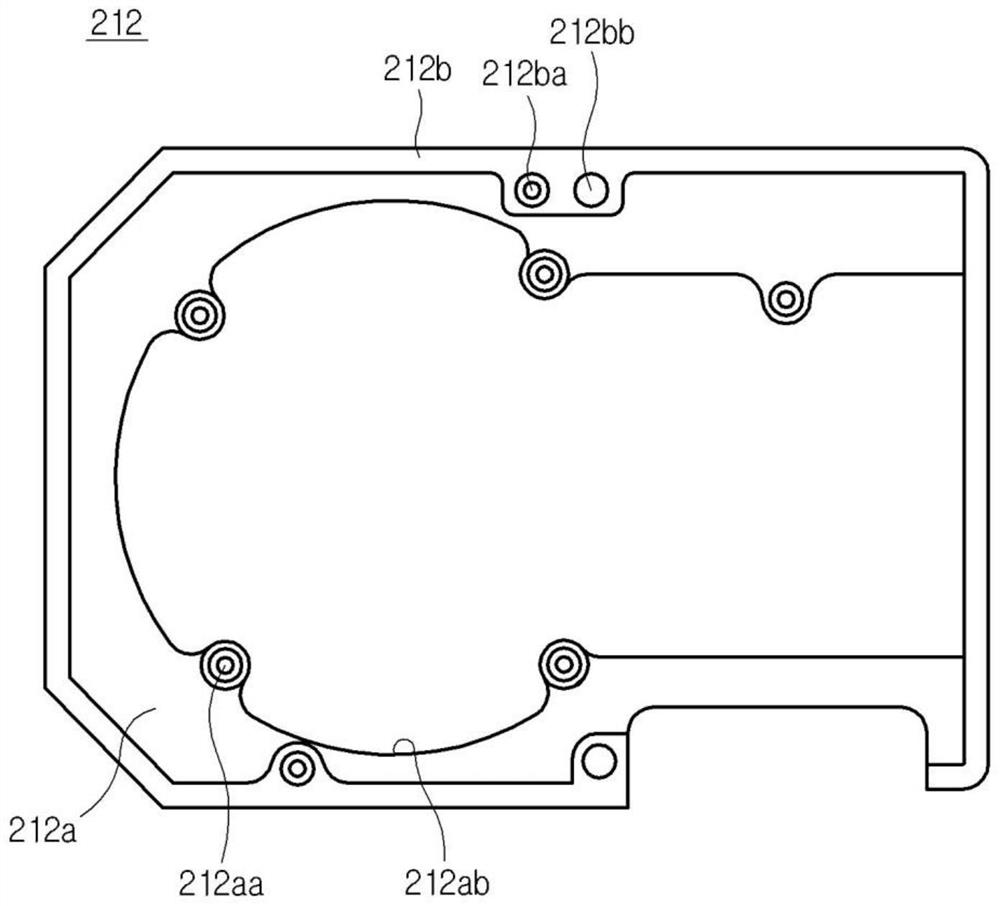
[0052] figure 1 A cross-sectional view showing an electric compressor applied to an embodiment of the present invention, figure 2 Is on one side of the frame figure 1 The electric compressor is shown in the inverter, image 3 Is pair in welding figure 1 A front view showing the first partition in the inverter manufacturing apparatus used in the inverter in the inverter. Figure 4 Is pair in welding figure 1 A front view of the second partition in the inverter manufacturing apparatus used in the inverter in the inverter, Figure 5 Yes Figure 4 Rear view, Image 6 is true figure 1 The motor compressor is placed in an inverter image 3 The state of the first partition is shown in the figure. Figure 7 is true Figure 4 as well as Figure 5 The second partition in the middle is combined to place Image...


PUM


Abstract

The present invention relates to an electric compressor, an inverter manufacturing apparatus and an inverter manufacturing method. An inverter of an electric compressor comprises: a substrate having a plurality of elements mounted thereon; and a frame coupled to the substrate. The frame comprises: a support plate; a side plate portion protruding from the support plate toward the substrate; an array plate on which switching elements connecting to the substrate are arrayed; and a connecting bar for connecting the support plate and array plate. The inverter manufacturing apparatus comprises: a first dummy plate fixed to the frame; and a second dummy plate which is coupled to the first dummy plate, comes into contact with the switching elements, and fixes the plurality of elements and switching elements and dissipates the heat thereof. The inverter manufacturing method comprises the steps of: placing an inverter on the first dummy plate; fixing the plurality of elements and switching elements by coupling the second dummy plate to the first dummy plate, and connecting the switching elements to a heat dissipation plate of the second dummy plate; and soldering the plurality of elements. Therefore, a soldering defect and element damage can be prevented.

Description

Technical field [0001] The present invention relates to an electric compressor, an inverter manufacturing apparatus, and an inverter manufacturing method, and more particularly to an electric compressor that prevents the element to take off and damage when the inverter of the electric compressor is welded. Multiple converter manufacturing apparatus and inverter manufacturing method. Background technique [0002] In general, the compressor used in the air-conditioning system of the car can perform the function of the evaporation of the evaporation from the evaporator and transferred to the condenser after converting it into a high temperature and high pressure state of the condenser. [0003] As described above, the compression operation is performed by a mechanical compressor that performs a compression operation by receiving a driving force from a vehicle, and an electric compression of the compression operation under driving of an electric motor (hereinafter referred to as a mo...

Claims


Application Information

Patent Timeline
Patent Type & Authority Applications(China)
IPC IPC(8): F04C23/02F04C29/00F04C29/04H02M7/00
CPCF04C23/02F04C29/04F04C29/00H02M7/003H05K7/20H02M7/00H02M7/44H02K11/33H02K5/18F04C18/0215F04C29/0085F04C2240/808F04C2230/231F04C29/047F04C2240/803
Inventor 李在澈
Owner HANON SYST
Why Eureka
Try Eureka