3D printing powder transfer device, 3D printer and using method

A 3D printing and transfer device technology, applied in the field of additive manufacturing, can solve the problems of poor powder blowing effect, small blowing range, and unable to blow powder, etc., to achieve good blowing effect, simple structure, and anti-oxidation Effect

Pending Publication Date: 2022-02-25
苏州三峰激光科技有限公司
View PDF2 Cites 0 Cited by
  • Summary
  • Abstract
  • Description
  • Claims
  • Application Information

AI Technical Summary

Problems solved by technology

However, there are obvious safety hazards in the use of this device: there is a risk of explosion when the powder in the airtight container is heated, especially when heating active powder such as aluminum powder
In addition, the purge pipe in the cavity of this product is located at the bottom of the powder storage bin, and the range that can be blown away is small. When there is a lot of powder, it is easy to blow the powder, and the powder blowing effect is poor.

Method used


Image

  • 3D printing powder transfer device, 3D printer and using method
  • 3D printing powder transfer device, 3D printer and using method
  • 3D printing powder transfer device, 3D printer and using method

Examples


Embodiment 1

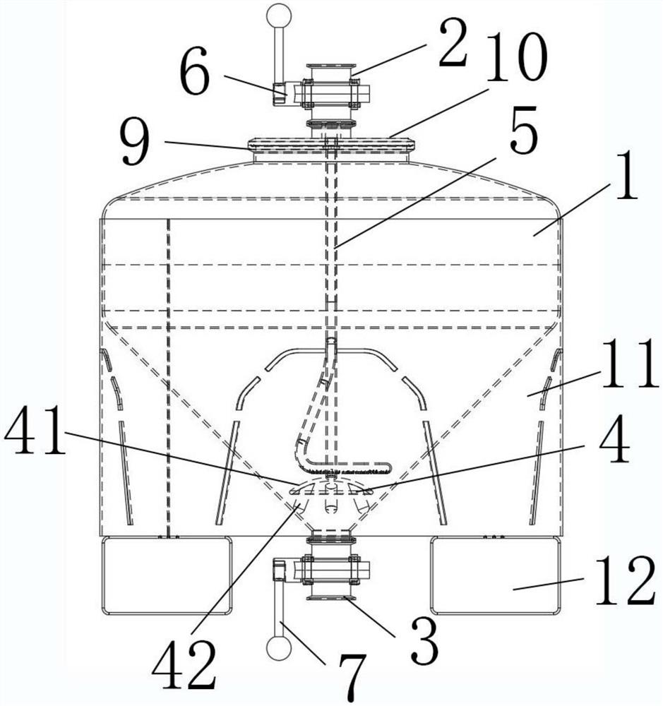
[0047] Such as Figure 1-Figure 3 As shown, an anti-oxidation and anti-blocking 3D printing powder transfer device, including

[0048] The powder storage bin 1 is used to store 3D printing powder, the top of the powder storage bin is provided with a powder inlet 2, and the bottom end is provided with a powder outlet 3, and the 3D printing powder in the powder storage bin flows from the powder inlet to the powder outlet ;

[0049] Buffer device 4, the buffer device is located at the bottom inside the powder storage bin;

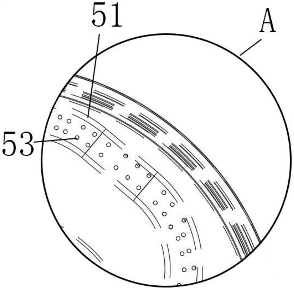
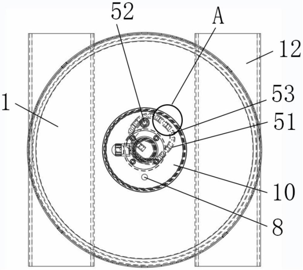
[0050] Gas inlet device 5; the gas inlet device is located inside the powder storage bin and one end is connected to the top of the powder storage bin, and the other end extends into the bottom of the powder storage bin and is located above the buffer device; the gas inlet The device is used to feed inert gas into the powder storage bin.

[0051] Further, the width of the powder storage bin gradually decreases from the end close to the powder inlet along th...

Embodiment 2

[0071] This embodiment is carried out on the basis of the first embodiment above, and the similarities with the above embodiment will not be repeated.

[0072] This embodiment mainly introduces an anti-oxidation and anti-clogging 3D printer compatible with Embodiment 1, including: a feeding device, a powder spreading device, and the anti-oxidation and anti-blocking 3D printing powder transfer device described in Embodiment 1. The powder inlet of the anti-oxidation and anti-blocking 3D printing powder transfer device is connected to the powder outlet of the feeding device, and the powder outlet of the anti-oxidation and anti-blocking 3D printing powder transfer device is connected to the powder spreading device. The powder inlet is connected.

[0073] Preferably, an inert gas supply device is included, and the inert gas supply device is connected to the inert gas inlet through a pipeline.

[0074] The method for using the 3D printer described in this embodiment includes the fo...


PUM


Abstract

The invention discloses a 3D printing powder transfer device, a 3D printer and a using method. The 3D printing powder transfer device comprises a powder storage bin, a buffer device and a gas introduction device, wherein the gas introduction device is located in the powder storage bin, one end of the gas introduction device is connected with the top of the powder storage bin, and the other end of the gas introduction device extends into the bottom end of the powder storage bin and is located above the buffer device; and the gas introduction device is used for introducing inert gas into the powder storage bin. The gas introduction device is arranged to introduce inert gas to be matched with the buffer device to purge powder so as to dry the powder, the powder is prevented from being in contact with air to be oxidized, the powder can be prevented from being blocked at a powder outlet, the dry powder is continuously and stably conveyed into printing equipment, efficient operation of powder laying printing work is ensured, and the production efficiency is further improved.

Description

technical field [0001] The invention relates to the technical field of additive manufacturing, in particular to a 3D printing powder transfer device, a 3D printer and a use method. Background technique [0002] At present, the feeding method of the upper powder feeding 3D printing system at home and abroad mostly adopts self-gravity dropping to the powder spreading device. The powder is conveyed in the powder mode. When the powder accumulates at the bottom powder outlet, the fine metal powder is easily oxidized and damp during the turnover process, which will make it difficult to open the powder outlet, and even cause the powder outlet control valve to jam and damage. While this type of device leads to a decline in product performance and stability, there is a problem that the powder outlet is blocked due to powder agglomeration, which leads to the problem that the continuous supply of materials cannot be continued, and eventually the printing work stops, which seriously res...

Claims


Application Information

Patent Timeline
IPC IPC(8): B22F12/50B22F12/70B33Y10/00B22F10/77B33Y40/00
CPCB22F12/50B22F12/70B22F10/77B33Y40/00B33Y10/00Y02P10/25
Inventor 施春宇金晓杰张达明
Owner 苏州三峰激光科技有限公司
Why Eureka
Try Eureka