Bearing pretightening force adjusting device, electric spindle and machine tool

A technology of bearing preload and adjustment device, applied in metal processing machinery parts, large fixed members, metal processing equipment, etc., can solve the problems of strict sealing requirements, complex structure, and inability to realize real-time bearing preload adjustment, etc. High reliability, simple device structure and good stability

Active Publication Date: 2022-03-01
GREE ELECTRIC APPLIANCES INC
View PDF11 Cites 3 Cited by
  • Summary
  • Abstract
  • Description
  • Claims
  • Application Information

AI Technical Summary

Problems solved by technology

[0004] Although this kind of scheme can realize the adjustment of the bearing preload, but the structure is complicated, the sealing requirements are strict, and the real-time preload adjustment of the bearing under different working conditions cannot be realized.

Method used


Image

  • Bearing pretightening force adjusting device, electric spindle and machine tool
  • Bearing pretightening force adjusting device, electric spindle and machine tool
  • Bearing pretightening force adjusting device, electric spindle and machine tool

Examples


Embodiment 1

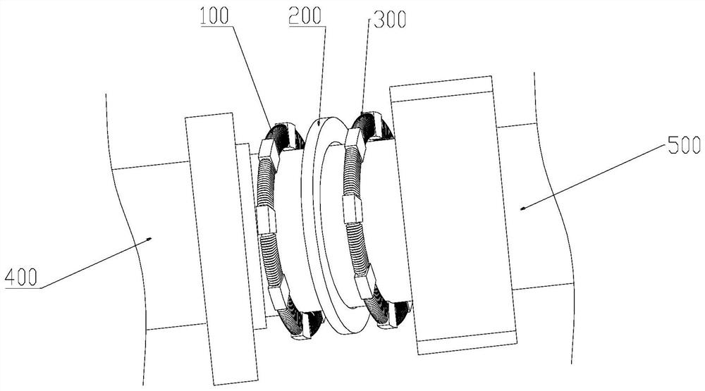
[0053] Such as Figure 1-Figure 5 As shown, a bearing pretightening force adjustment device includes: a driving power supply, a first electromagnetic coil 100 sleeved on a shaft body 400, a magnetostrictive element 200 and a second electromagnetic coil 300, and the magnetostrictive element 200 is located at Between the first electromagnetic coil 100 and the second electromagnetic coil 300 . The accompanying drawings of this application do not show the driving power supply. The preload adjusting device is arranged on the bearing 500 side of the shaft body 400, and the first electromagnetic coil 100 and the second electromagnetic coil 300 are used to generate a magnetic field with adjustable strength. More specifically, the driving power is connected to a current regulator, and the current regulator is electrically coupled to the first electromagnetic coil 100 and the second electromagnetic coil 300 respectively. The operator adjusts the magnitude of the current flowing throug...

Embodiment 2

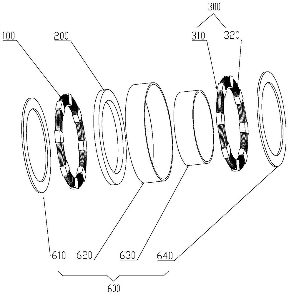
[0081] Such as Figure 6-7 As shown, this embodiment only describes the differences from Embodiment 1, and the rest of the technical features are the same as those of the above embodiment. Further, the magnetostrictive element 200 includes M stretchable blocks 210, where M is an integer greater than one, and where M and N are equal or different. That is, the number of the telescopic blocks 210 is the same as or different from the number of the supporting blocks on the first electromagnetic coil 100 or the second electromagnetic coil 300 . As a more optimal implementation manner, the number of the telescopic blocks 210 is the same as the number of support blocks on any electromagnetic coil. The telescopic block 210 is made of magnetorheological elastomer material, and the telescopic block 210 is fixed on the first support block 110 or the second support block 310 . Further, the first support block 110 and the second support block 310 are provided with positioning protrusions ...

Embodiment 3

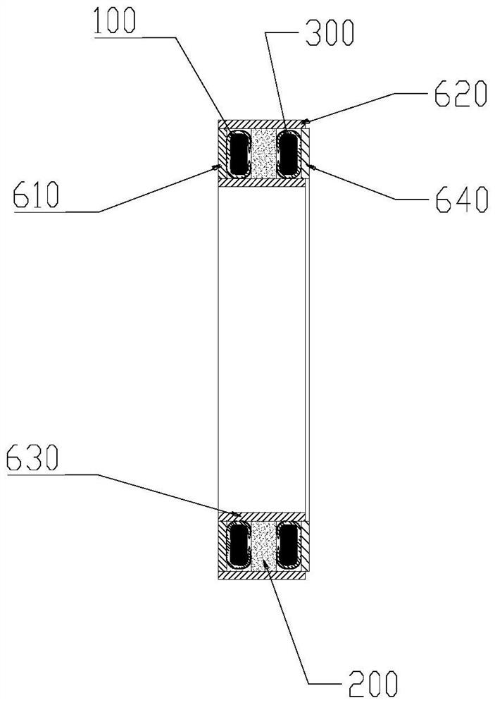
[0084] Such as Figure 6 As shown, this embodiment only describes the differences from Embodiment 1, and the rest of the technical features are the same as those of the above embodiment. Further, the magnetic isolation cover 600 includes an annular magnetic isolation main body 650 and a third cover plate 660, the magnetic isolation main body 650 is arranged on the shaft body 400, and the magnetic isolation main body 650 is provided with an annular housing Cavity 651, one side of the accommodating cavity 651 is open, and the third cover plate 660 is provided at the opening of the accommodating cavity 651;

[0085] The first electromagnetic coil 100 , the magnetostrictive element 200 and the second electromagnetic coil 300 are all disposed in the accommodating cavity 651 , and when the magnetostrictive element 200 expands and contracts axially, the third cover plate 660 Due to the expansion and contraction of the magnetostrictive element 200 , it moves along the axial direction...


PUM


Abstract

The invention provides a bearing pre-tightening force adjusting device, and belongs to the technical field of machine tool equipment, the adjusting device comprises a driving power supply, a first electromagnetic coil, a magnetostrictive part and a second electromagnetic coil, the first electromagnetic coil, the magnetostrictive part and the second electromagnetic coil are sleeved on a shaft body, and the magnetostrictive part is located between the first electromagnetic coil and the second electromagnetic coil. When the driving power source drives the magnetic field intensity between the first electromagnetic coil and the second electromagnetic coil to change, the magnetostriction piece generates axial expansion and contraction in the axial direction of the shaft body, and axial acting force is applied to the bearing of the shaft body. The adjusting device can adjust the pre-tightening force of the bearing in real time according to different working conditions of the motorized spindle, and is simple in structure, good in stability and high in reliability. The invention further provides an electric spindle comprising the bearing pretightening force adjusting device and a machine tool.

Description

technical field [0001] The invention relates to the technical field of machine tool equipment, in particular to a bearing pretightening force adjustment device, an electric spindle and a machine tool. Background technique [0002] High speed and precision have always been the goal of the development of machine tools. As the core component of machine tools, the electric spindle integrates the machine tool spindle and the spindle motor to realize the "zero transmission" of the machine tool, which has an important impact on the machining accuracy and efficiency of the machine tool. Under different working conditions, the electric spindle has different requirements for temperature rise and support rigidity, so different bearing preloads are required to adapt to it. Appropriate bearing preload can not only effectively control the temperature rise of the bearing, improve the bearing life, but also greatly improve the noise and vibration. [0003] The publication number is CN11163...

Claims


Application Information

Patent Timeline
Patent Type & Authority Applications(China)
IPC IPC(8): B23B19/02
CPCB23Q1/70Y02E10/72
Inventor 文智明张荣婷彭诚张庭政贾惠玲张冬冬
Owner GREE ELECTRIC APPLIANCES INC
Why Eureka
Try Eureka