
Yarn tension non-contact real-time detection control system and method based on machine vision

A technology of yarn tension and machine vision, which is applied in the field of non-contact real-time detection and control system of yarn tension based on machine vision, can solve problems affecting fabric quality, yarn breakage, and yarn tension fluctuations, and achieve long service life and equipment The effect of low failure rate and quality improvement

Active Publication Date: 2022-03-01
TIANJIN POLYTECHNIC UNIV
View PDF14 Cites 0 Cited by
  • Summary
  • Abstract
  • Description
  • Claims
  • Application Information

AI Technical Summary

Problems solved by technology

[0004] In view of this, the present invention aims to propose a non-contact real-time detection and control system of yarn tension based on machine vision, which can detect yarn tension more accurately and quickly Thread tension, and feed back the detection results to the controller for real-time control of the yarn tension, so as to solve the problems of yarn tension fluctuations, yarn breakage, and yarn stoppage in the knitting production process that are affected by tension changes and fabric quality.

Method used


Image

  • Yarn tension non-contact real-time detection control system and method based on machine vision
  • Yarn tension non-contact real-time detection control system and method based on machine vision
  • Yarn tension non-contact real-time detection control system and method based on machine vision

Examples


Embodiment Construction

[0034] It should be noted that, in the case of no conflict, the embodiments of the present invention and the features in the embodiments can be combined with each other.

[0035] In describing the present invention, it should be understood that the terms "center", "longitudinal", "transverse", "upper", "lower", "front", "rear", "left", "right", " The orientations or positional relationships indicated by "vertical", "horizontal", "top", "bottom", "inner" and "outer" are based on the orientations or positional relationships shown in the drawings, and are only for the convenience of describing the present invention and Simplified descriptions, rather than indicating or implying that the device or element referred to must have a particular orientation, be constructed and operate in a particular orientation, and thus should not be construed as limiting the invention. In addition, the terms "first", "second", etc. are used for descriptive purposes only, and should not be understood ...


PUM


Abstract

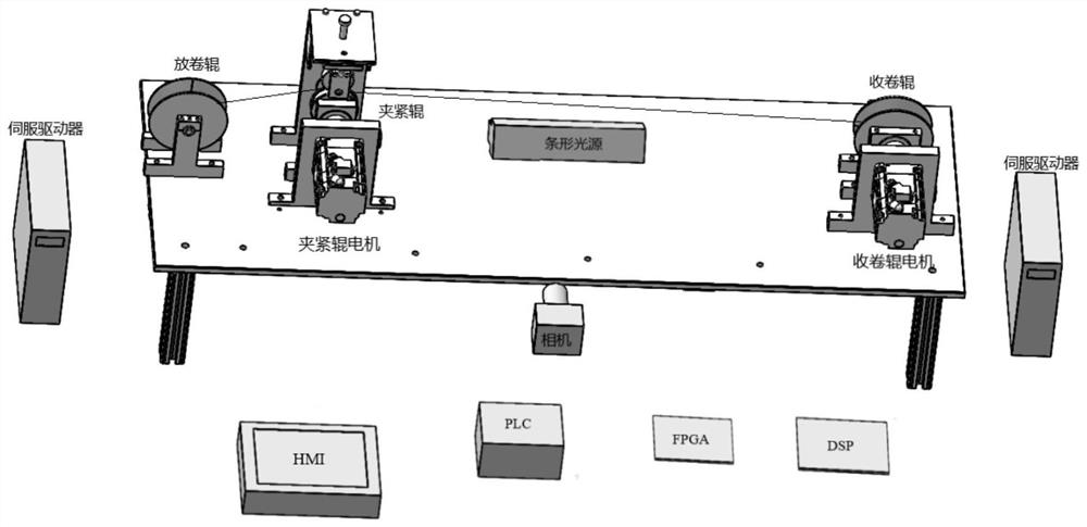
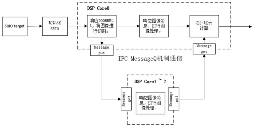
The invention provides a non-contact yarn tension real-time detection control system based on a machine vision technology by taking a CCD (Charge Coupled Device) camera and a DSP (Digital Signal Processor) + FPGA (Field Programmable Gate Array) architecture as an image processor and a PCL (Programmable Logic Controller) as a motor controller. The method comprises the following steps: firstly, acquiring an image of a yarn in a motion state by a linear array CCD (Charge Coupled Device) camera, and transmitting image data to a DSP (Digital Signal Processor) embedded processor by an FPGA embedded processor; the DSP performs basic processing on the image, models the image and calculates the tension of the yarn; finally, a calculation result on the DSP is fed back to a PCL motor controller, a yarn winding roller motor is controlled, and a closed-loop control system of the yarn tension is formed. The system measures and controls the tension of the yarn in real time, when the detection value of the tension of the yarn does not accord with the specified value, the running speed of the yarn is regulated, the tension is fed back, and finally the actual tension value of the tension of the yarn is consistent with the ideal set value.

Description

technical field [0001] The invention belongs to the field of yarn tension detection, and in particular relates to a non-contact real-time detection and control system and method of yarn tension based on machine vision. Background technique [0002] All textile products have requirements for their tension during the production process, and it is required to precisely control the yarn tension in textile manufacturing to ensure product quality and production efficiency. The tension of the yarn not only affects the quality of the finished product, whether the dyeing is uniform, etc., but may even seriously reduce the production capacity and cause unnecessary losses to the production equipment. Therefore, it is of great significance to the weaving industry to detect and control the yarn tension correctly and efficiently. [0003] According to the contact state during yarn tension detection, the tension detection method can be divided into contact type and non-contact type. At pr...

Claims


Application Information

Patent Timeline
IPC IPC(8): B65H59/38
CPCB65H59/385B65H2701/31
Inventor 纪越蔡佳茏宋丽梅马杰东陈文姚赵文浩
Owner TIANJIN POLYTECHNIC UNIV
Learn More