System and process for realizing zero discharge of wastewater by contacting dry and cold carrier gas with hot wastewater

A hot wastewater and zero-discharge technology, applied in the direction of heating water/sewage treatment, water/sewage treatment, water/sludge/sewage treatment, etc., can solve the problem of thermal scale blockage in the system, high energy consumption of induced draft fans and spray circulation pumps , bulky and other problems, to achieve the effect of low power consumption, saving energy costs, and superior operating parameters

Active Publication Date: 2022-03-01
SHANDONG GUOSHUN CONSTR GRP
View PDF6 Cites 0 Cited by
  • Summary
  • Abstract
  • Description
  • Claims
  • Application Information

AI Technical Summary

Problems solved by technology

However, the flue gas waste heat evaporator is just like a small wet desulfurization system, which receives the acid gas and productive dust brought by the flue gas, causing system blockage, complicated operation, high energy consumption of induced draft fans and spray circulation pumps, etc. The most serious problems are: a) direct contact between waste water and the introduced hot flue gas, which may easily cause the risk of hot scale blockage in the system; b) hot flue gas cannot be discharged directly after it becomes wet flue gas, It must also be sent back to the original extraction point, which makes the system complicated; c) when the hot flue gas is in direct contact with the waste water, the salt in the flue gas (in the form of chlorine Cl - Salt-based) transferred to waste water, when the concentration is too high, electrochemical corrosion will occur to the operating equipment; d) The flue gas evaporation device adopts spraying method for direct gas-liquid contact. When the flue gas inlet temperature is greater than 100 ° C, It is difficult for the hot flue gas to mix evenly with the waste water, and it is easy to cause the local waste water to evaporate rapidly, resulting in the rapid precipitation of salt, which in turn leads to the occurrence of thermal scale blockage; e) The flue gas carries a certain amount of acid gas and dust, so the flue gas evaporation device The mist eliminator needs to be washed with clean water frequently, which leads to a certain degree of reduction in the evaporative concentration effect on wastewater; f) the high water content in the hot flue gas limits the ability to carry water when evaporatively concentrating wastewater
The problems of this type of process are: 1) This type of process is based on the gas-gas heat exchanger, that is, the heat exchange between the waste heat carrier (such as hot flue gas) and air, thereby realizing the transfer of enthalpy
Therefore, there are defects that the equipment is very bulky and the heat exchange efficiency is relatively low, which is not even as good as the second type of process mentioned above; 2) When the hot air is used to directly contact the sprayed wastewater for heat exchange, the temperature of the hot air is relatively high, and it is difficult to communicate with it The uniform contact of wastewater causes the hot air to locally heat the wastewater, resulting in the rapid evaporation of the local wastewater, and the rapid increase of the salt concentration in this part of the wastewater, which easily leads to salt precipitation and the occurrence of thermal scale blockage.

Method used


Image

  • System and process for realizing zero discharge of wastewater by contacting dry and cold carrier gas with hot wastewater
  • System and process for realizing zero discharge of wastewater by contacting dry and cold carrier gas with hot wastewater
  • System and process for realizing zero discharge of wastewater by contacting dry and cold carrier gas with hot wastewater

Examples


Embodiment Construction

[0075] It should be noted that the following detailed description is exemplary and intended to provide further explanation of the present invention. Unless defined otherwise, all technical and scientific terms used herein have the same meaning as commonly understood by one of ordinary skill in the art to which this invention belongs.

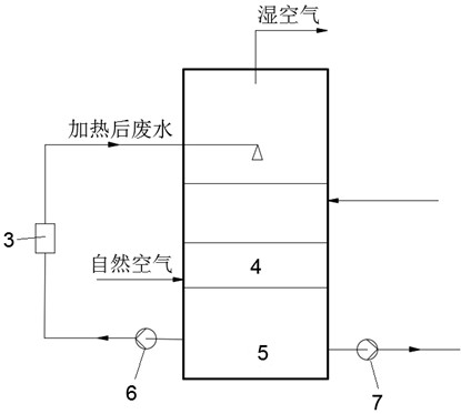
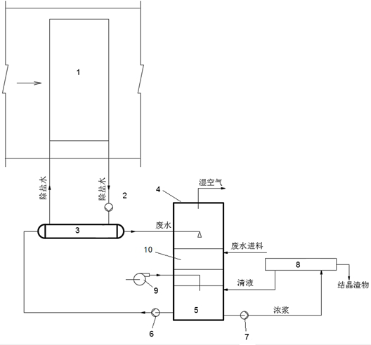
[0076] Such as figure 1 and figure 2 As shown, a system that uses dry and cold carrier gas in contact with hot wastewater to achieve zero discharge of wastewater, a heat exchange device for heating wastewater, and its wastewater outlet is connected to the spray layer on the top of the evaporation device;

[0077] The bubbling device is installed at the gas-liquid contact part inside the evaporation device, and its dry and cold air nozzle is inserted below the liquid level of the hot wastewater;

[0078] The fan, whose inlet is connected with the gas source, and whose outlet is connected with the gas inlet of the bubbling device, is used to pr...


PUM


Abstract

The invention discloses a system and a process for realizing zero discharge of wastewater by contacting dry and cold carrier gas with hot wastewater, comprising: a heat exchange device for heating wastewater, a wastewater outlet of which is connected with a spray layer at the top of an evaporation device; the bubbling device is arranged in the evaporation device, and a nozzle of the bubbling device is inserted into wastewater; an inlet of the fan is communicated with a gas source, an outlet of the fan is connected with a gas inlet of the bubbling device, and the fan is used for providing dry and cold carrier gas for the bubbling device; the straight-through flow guide device comprises a plurality of liquid distribution elements which are vertically arranged in parallel, and the straight-through flow guide device is arranged in the evaporation device and located above the preset liquid level of the wastewater. The dry and cold carrier gas is subjected to shallow bubbling below the wastewater liquid level of the evaporation device through the bubbling device to generate a main concentration process. The temperature and the humidity of the carrier gas after the main concentration process are increased, the evaporation efficiency of the waste water is reduced, at the moment, secondary heat exchange and mass transfer are carried out on the carrier gas and the sprayed waste water in the straight-through flow guide device, and the straight-through flow guide device can be effectively prevented from being scaled and blocked.

Description

technical field [0001] The invention belongs to the technical field of wastewater treatment, and in particular relates to a system and a process for realizing zero discharge of wastewater by using dry and cold carrier gas in contact with hot wastewater. Background technique [0002] The statements herein merely provide background information related to the present invention and do not necessarily constitute prior art. [0003] In the production of process systems in the power industry and metallurgical industry, continuous discharge of wastewater is often unavoidable in the production process. For example, the number of enterprises adopting wet desulfurization process is large. In order to maintain the normal operation of desulfurization equipment, the desulfurization system needs to continuously discharge wastewater with high concentration of salt and high concentration of pollutants, so that enterprises have to continuously replenish fresh process water, and It takes a lo...

Claims


Application Information

Patent Timeline
Patent Type & Authority Applications(China)
IPC IPC(8): C02F1/10C02F1/04
CPCC02F1/10C02F1/042C02F1/043C02F1/048C02F2209/02C02F2303/10Y02A20/124
Inventor 刘述平吕扬马松杨凤岭孙德山管闯仇洪波尹鹏陈向波冯超吕和武蔡延民王国威
Owner SHANDONG GUOSHUN CONSTR GRP
Why Eureka
Try Eureka