Full-quantification landfill leachate treatment system and treatment method
A landfill leachate and treatment system technology, applied in the field of fully quantified landfill leachate treatment system, can solve the problems of carbon-nitrogen ratio imbalance, high conductivity of raw water, short operating life of membrane system, etc., to ensure operating life and improve work efficiency Effect
- Summary
- Abstract
- Description
- Claims
- Application Information
AI Technical Summary
Problems solved by technology
Method used
Image

Examples
Embodiment Construction
[0032] The following will clearly and completely describe the technical solutions in the embodiments of the present invention with reference to the accompanying drawings in the embodiments of the present invention. Obviously, the described embodiments are only some, not all, embodiments of the present invention. Based on the embodiments of the present invention, all other embodiments obtained by persons of ordinary skill in the art without making creative efforts belong to the protection scope of the present invention.
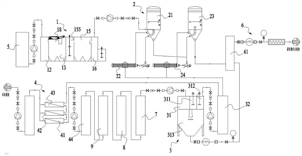
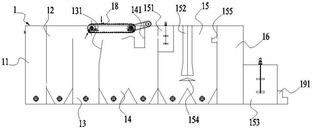
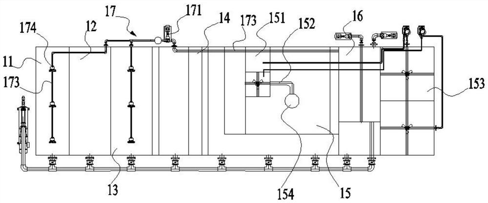
[0033] see figure 1 The embodiment of the present invention provides a fully quantified landfill leachate treatment system for realizing the whole process treatment of landfill leachate, including a pretreatment device 1 , an evaporation device 2 , a leachate advanced treatment device 3 and a membrane treatment device 4 . Among them, the pretreatment device 1 is used for preliminary treatment of landfill leachate; the evaporation device 2 is used for evaporati...
PUM
 Abstract
Description
Claims
Application Information