
Use method of dust coagulation device based on gas atomization vortex fluid generation unit group

A generation unit and aerosolization technology, applied in chemical instruments and methods, safety devices, separation methods, etc., can solve the problem of gradient difference between surface tensions, etc., achieve strong self-containment ability, efficient dust condensation process, Implement effects with large spatial and temporal interval scales

Active Publication Date: 2022-03-01
TAIYUAN UNIV OF TECH
View PDF8 Cites 0 Cited by
  • Summary
  • Abstract
  • Description
  • Claims
  • Application Information

AI Technical Summary

Problems solved by technology

[0009] The purpose of the present invention is to use a dust coalescing device based on an aerosolized vortex fluid generating unit group to solve the existing and unsolvable problems in the above-mentioned prior art, thereby attempting to disclose a method for the Marangoni force action. Next, relying on the self-consumption ability of the generated fluid and the ability to adapt to complex applications, the individual units generated by the aerosolized vortex fluid are combined to form a multi-unit combination group. With the help of the inhomogeneity between the units, the combination During the flow process, the group controls and adjusts the alternating change of the solid-liquid-gas three-phase state, so that a gradient difference is formed between the surface tensions of different phase fluids. Tiny water droplets gather and separate out, complete reliable condensation, produce unexpected effect energy superposition to achieve efficient dust removal device

Method used


Image

  • Use method of dust coagulation device based on gas atomization vortex fluid generation unit group

Examples


Embodiment approach 1

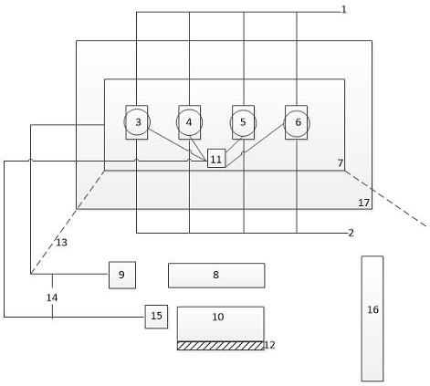
[0041] The device consists of pressure water circuit 1, pressure gas circuit 2, gas atomization vortex fluid generator A 3, gas atomization vortex fluid generator B 4, gas atomization vortex fluid generator C 5, gas atomization vortex Fluid generator D 6, aerosolized vortex fluid penetration angle regulator 7, tiny water droplet nuclei 8, tiny water droplet nucleation generation state observer 9, frustration process 10, vortex fluid outlet temperature fine-tuning device 11, surface tension gradient Poor process 12, dust generation control space 13, feedback control signal line 14, gas atomization vortex fluid condensation feedback device 15, gas atomization vortex group fluid 16, aerosol generation unit combination group 17, gas atomization vortex Swirl fluid generator A 3, gas atomization vortex fluid generator B 4, gas atomization vortex fluid generator C 5, and gas atomization vortex fluid generator D 6 are respectively provided with pressure gas pressure water on both sides...

Embodiment approach 2

[0050] The device consists of pressure water circuit 1, pressure gas circuit 2, gas atomization vortex fluid generator A 3, gas atomization vortex fluid generator B 4, gas atomization vortex fluid generator C 5, gas atomization vortex Fluid generator D 6, aerosolized vortex fluid penetration angle regulator 7, tiny water droplet nuclei 8, tiny water droplet nucleation generation state observer 9, frustration process 10, vortex fluid outlet temperature fine-tuning device 11, surface tension gradient Poor process 12, dust generation control space 13, feedback control signal line 14, gas atomization vortex fluid condensation feedback device 15, gas atomization vortex group fluid 16, aerosol generation unit combination group 17, gas atomization vortex Swirl fluid generator A 3, gas atomization vortex fluid generator B 4, gas atomization vortex fluid generator C 5, and gas atomization vortex fluid generator D 6 are respectively provided with pressure gas pressure water on both sides...

Embodiment approach 3

[0059] The device consists of pressure water circuit 1, pressure gas circuit 2, gas atomization vortex fluid generator A 3, gas atomization vortex fluid generator B 4, gas atomization vortex fluid generator C 5, gas atomization vortex Fluid generator D 6, aerosolized vortex fluid penetration angle regulator 7, tiny water droplet nuclei 8, tiny water droplet nucleation generation state observer 9, frustration process 10, vortex fluid outlet temperature fine-tuning device 11, surface tension gradient Poor process 12, dust generation control space 13, feedback control signal line 14, gas atomization vortex fluid condensation feedback device 15, gas atomization vortex group fluid 16, aerosol generation unit combination group 17, gas atomization vortex Swirl fluid generator A 3, gas atomization vortex fluid generator B 4, gas atomization vortex fluid generator C 5, and gas atomization vortex fluid generator D 6 are respectively provided with pressure gas pressure water on both sides...


PUM


Abstract

A use method of a dust coagulation device based on a gas atomization vortex fluid generation unit group belongs to the technical field of fluid application, and is characterized in that individual units generated by gas atomization vortex fluid are combined to form a multi-unit combination group under the action of Malangei force by relying on the self-absorption capability of the generated fluid, and the multi-unit combination group is used for generating the dust coagulation device based on the gas atomization vortex fluid generation unit group. By means of non-uniformity among the units, gradient difference is formed among surface tensions of fluids of different phases by controlling and adjusting alternate change of solid, liquid and gas phases in the flowing process of a combination group, and a large number of dust microparticles in gas atomization fluid are gathered towards tiny water drops and separated out in the close contact process of all the phase states. According to the device, reliable coagulation is completed, unexpected effect energy superposition is generated to achieve efficient dust removal, and the dust capturing capacity of a multi-unit combination group is improved by 2-3 orders of magnitude compared with the dust capturing capacity of a single unit.

Description

technical field [0001] The invention discloses a method for using a dust coalescing device based on an aerosolized vortex fluid generating unit group, which belongs to the technical field of fluid application, and specifically relates to a self-containing fluid generated under the action of Marangoni force Ability, through the combination of individual units generated by aerosolized vortex fluid, a multi-unit combination group is formed. With the help of the inhomogeneity among its units, the combination group alternately changes the solid-liquid-gas three-phase state during the flow process The control adjustment makes the gradient difference between the surface tension of different phase fluids. During the close contact process of each phase state, a large number of dust particles in the aerosolized fluid gather and separate from the tiny water droplets, and complete reliable condensation, resulting in unexpected The superposition of the effect energy to achieve high-efficie...

Claims


Application Information

Patent Timeline
Patent Type & Authority Applications(China)
IPC IPC(8): E21F5/04B01D47/06
CPCE21F5/04B01D47/06
Inventor 郭建珠赵晓兵何艳
Owner TAIYUAN UNIV OF TECH
Learn More