Illuminating lamp and using method thereof
A technology for lighting lamps and LED light sources, applied in lighting devices, lighting and heating equipment, headlights, etc., can solve problems such as limited and low system efficiency, and achieve the effect of improving light efficiency, reducing light efficiency, and overcoming insufficient brightness.
- Summary
- Abstract
- Description
- Claims
- Application Information
AI Technical Summary
Problems solved by technology
Method used
Image
Examples
Embodiment 1
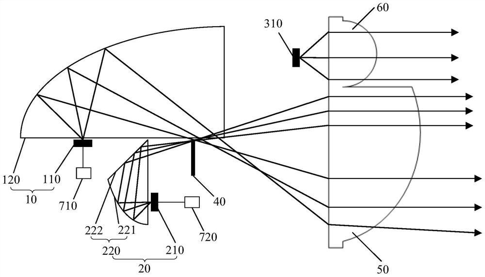
[0032] Such as figure 1 As shown, the present invention provides a lighting fixture, which includes a first light source group 10 , a second light source group 20 , a third light source group, a shading sheet 40 and a first lens 50 .
[0033] Wherein, the first light source group 10 includes a first LED light source 110 and a first reflective cup 120 corresponding to the first LED light source 110 , the light emitted by the first LED light source 110 is reflected by the first reflective cup 120 Shoots in the specified direction. There can be multiple first LED light sources 110 , the positions of which correspond to the focus of the first reflective cup 120 , and the light emitted by the first LED light source 110 is reflected by the first reflective cup 120 before being emitted.
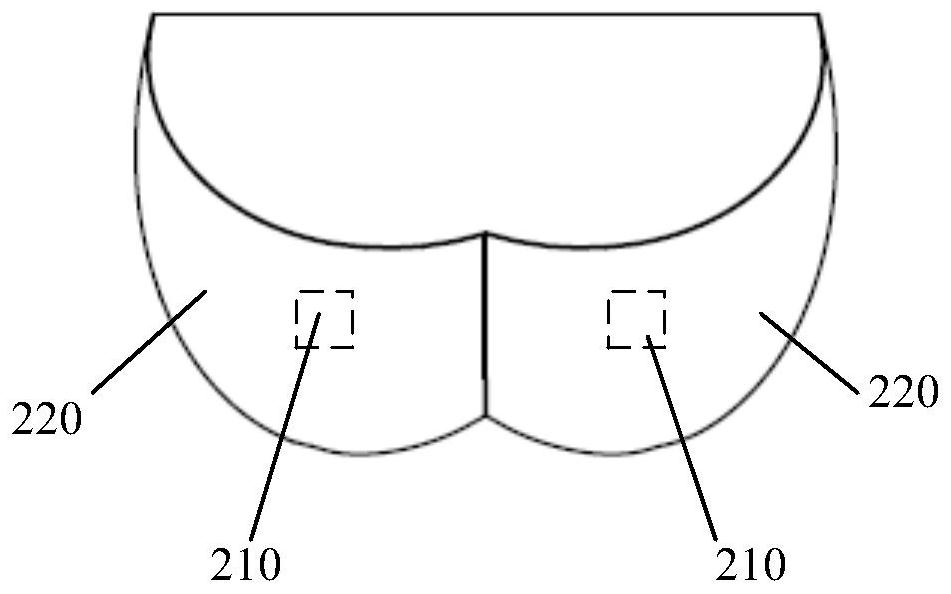
[0034] The second light source group 20 includes a second LED light source 210 and an optical path turning member 220 corresponding to the second LED light source 210. The optical path turning memb...
Embodiment 2
[0042] Such as Figure 4 As shown, different from Embodiment 1, in this embodiment, the third light source group further includes a third reflective cup 320 corresponding to the third light source 310, and the light emitted by the third light source 310 passes through the first After being reflected by the three reflective cups 320 , it emits along a designated direction and forms a strip-shaped light field distribution, and the light distribution is all located below the low beam cut-off line for assisting low beam lighting. Specifically, in this embodiment, the third reflective cup 320 also corresponds to the vacant part of the first lens 50 . The light emitted from the third light source 310 can pass through the third reflector 320 and exit in parallel obliquely downward, and the formed luminous flux is located below the cut-off line of the low beam, improving the central illuminance of the low beam lighting.
Embodiment 3
[0044] Such as Figure 5 As shown, different from Embodiment 2, in this embodiment, the second light source group 20 further includes a laser light source 230 , and the light emitted by the laser light source 230 is projected onto the phosphor sheet of the second LED light source 210 . The first reflective surface 221 is an ellipsoid or an approximate ellipsoid, and the second reflective surface 222 is a plane reflective surface. The light hole is located on the ellipsoidal surface, and the second LED light source 210 includes an LED chip 211 and a phosphor sheet 212 corresponding to the LED chip 211. The light emitted by the laser light source 230 passes through the light hole and then projects to the second LED. On the phosphor sheet 212 of the light source 210, when there are two second LED light sources 210, there may be only one laser light source 230, which is projected onto one of the second LED light sources 210. Of course, two laser light sources 240 may also be provi...
PUM
 Abstract
Description
Claims
Application Information
 - R&D
- Intellectual Property
- Life Sciences
- Materials
- Tech Scout
- Unparalleled Data Quality
- Higher Quality Content
- 60% Fewer Hallucinations
Browse by: Latest US Patents, China's latest patents, Technical Efficacy Thesaurus, Application Domain, Technology Topic, Popular Technical Reports.
© 2025 PatSnap. All rights reserved.Legal|Privacy policy|Modern Slavery Act Transparency Statement|Sitemap|About US| Contact US: help@patsnap.com


