
Pole piece strip drying device

A drying device and strip technology, which is applied in drying solid materials, drying cargo handling, drying chamber/container, etc., can solve the problems of increasing the number of input equipment, waste of production capacity and resources, easy to be unevenly heated, etc., and achieve long heating time. , The effect of heating evenly and saving drying time

Pending Publication Date: 2022-03-01
向江雄
View PDF0 Cites 0 Cited by
  • Summary
  • Abstract
  • Description
  • Claims
  • Application Information

AI Technical Summary

Problems solved by technology

[0003] There are two types of drying equipment currently in production, one is to bake the material under normal pressure, and the other is to bake the whole roll in a vacuum box. The two baking methods take a long time and are easy to be heated Uniform, although these mechanisms can roughly meet the requirements of use, but the efficiency is too slow, resulting in a waste of production capacity and resources. If you want to increase production capacity, you can only increase the number of equipment invested, resulting in high overall costs

Method used

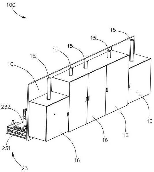
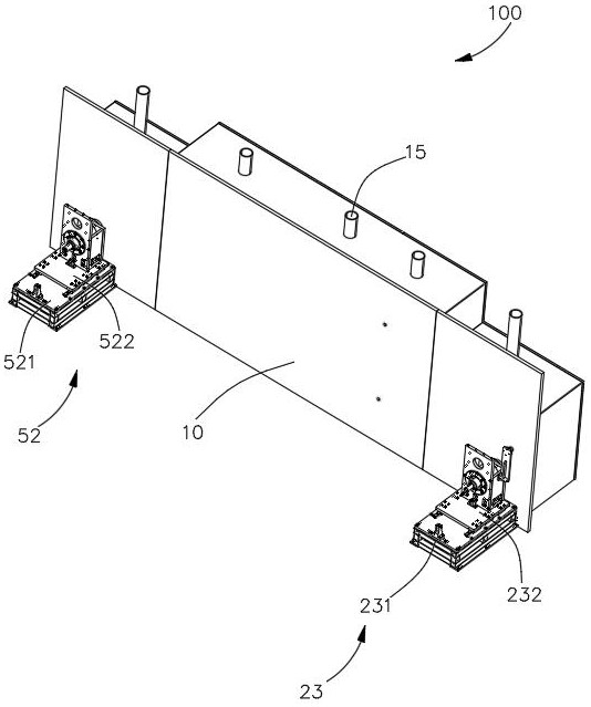
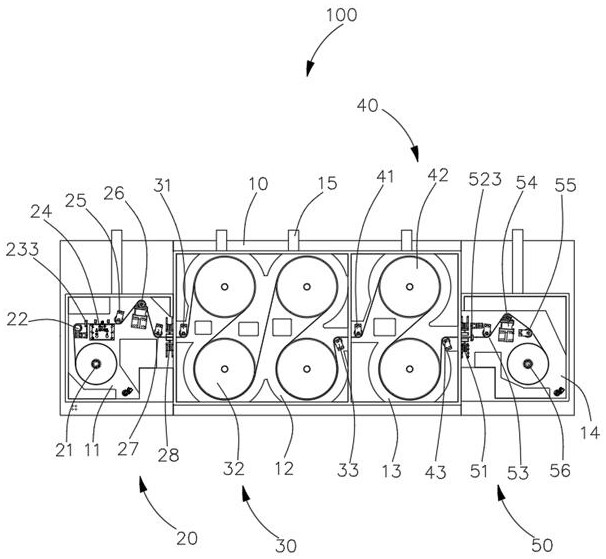

Image

  • Pole piece strip drying device
  • Pole piece strip drying device
  • Pole piece strip drying device

Examples


Embodiment Construction

[0032] In order to make the above objects, features and advantages of the present invention more comprehensible, specific implementations of the present invention will be described in detail below in conjunction with the accompanying drawings. In the following description, numerous specific details are set forth in order to provide a thorough understanding of the present invention. However, the present invention can be implemented in many other ways different from those described here, and those skilled in the art can make similar improvements without departing from the connotation of the present invention, so the present invention is not limited by the specific embodiments disclosed below.

[0033] It should be noted that when an element is referred to as being “fixed” to another element, it can be directly on the other element or there can also be an intervening element. When an element is referred to as being "connected to" another element, it can be directly connected to t...


PUM


Abstract

The pole piece strip drying device comprises a machine box, an unwinding mechanism, a drying mechanism, a cooling mechanism and a winding mechanism, the unwinding mechanism, the drying mechanism, the cooling mechanism and the winding mechanism are sequentially arranged in the machine box, a feeding chamber, a drying chamber, a cooling chamber and a material collecting chamber are formed in the machine box at intervals, and the feeding chamber, the drying chamber, the cooling chamber and the material collecting chamber all communicate with vacuum exhaust pipes; the unwinding mechanism is arranged in the feeding chamber and used for releasing wound pole piece strips, the drying mechanism is arranged in the drying chamber and comprises a plurality of heating rollers arranged at intervals, the pole piece strips are sequentially wound around the heating rollers and used for heating and drying the pole piece strips, the cooling mechanism is arranged in the cooling chamber and comprises a plurality of cooling rollers arranged at intervals, and the cooling rollers are used for cooling the pole piece strips. The pole piece strip is sequentially wound around the cooling rollers and used for cooling the dried pole piece strip, and the winding mechanism is arranged in the material receiving chamber and used for recycling and coiling the dried and cooled pole piece strip; the pole piece strip drying device has the advantages of being high in heating efficiency and low in energy consumption.

Description

technical field [0001] The invention relates to the technical field related to the manufacture of lithium batteries, in particular to a pole piece strip drying device. Background technique [0002] At present, the lithium battery industry at home and abroad has a good development prospect. Lithium-ion batteries have been widely used in portable electrical appliances such as laptop computers, cameras, and mobile communications due to their unique performance advantages. The currently developed high-capacity lithium-ion battery has been tested in electric vehicles and is expected to become one of the main power sources for electric vehicles in the 21st century, and will be more widely used in satellites, aerospace and energy storage. With the shortage of energy and the huge pressure on the world's environmental protection. Lithium batteries are now widely used in the electric vehicle industry, especially the emergence of lithium iron phosphate batteries, which has promoted th...

Claims


Application Information

Patent Timeline
Patent Type & Authority Applications(China)
IPC IPC(8): F26B3/347F26B5/04F26B13/08F26B13/12F26B13/18F26B25/00F26B25/12F26B25/18
CPCF26B13/08F26B13/183F26B5/047F26B13/12F26B25/003F26B25/18F26B25/12F26B25/008F26B3/347
Inventor 向江雄
Owner 向江雄
Learn More